Nissan Maxima Service and Repair Manual: Power supply and ground circuit
BCM
BCM : Diagnosis Procedure
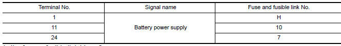
1. CHECK FUSE AND FUSIBLE LINK
Check if the following BCM fuses or fusible link are blown.
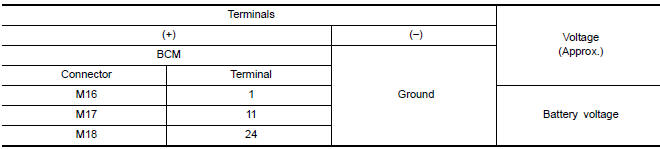
2. CHECK POWER SUPPLY CIRCUIT
- Turn ignition switch OFF.
- Disconnect BCM.
- Check voltage between BCM harness connector and ground.
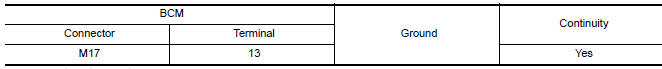
3. CHECK GROUND CIRCUIT
Check continuity between BCM harness connector and ground.
BCM : Special Repair Requirement
1. REQUIRED WORK WHEN REPLACING BCM
IPDM E/R (INTELLIGENT POWER DISTRIBUTION MODULE ENGINE ROOM)
IPDM E/R (INTELLIGENT POWER DISTRIBUTION MODULE ENGINE ROOM) : Diagnosis Procedure
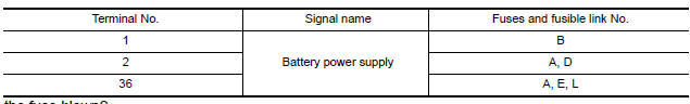
1. CHECK FUSES AND FUSIBLE LINK
Check that the following IPDM E/R fuses or fusible link are not blown.
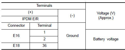
2. CHECK POWER SUPPLY CIRCUIT
- Turn ignition switch OFF.
- Disconnect IPDM E/R connectors.
- Check voltage between IPDM E/R harness connector and ground.
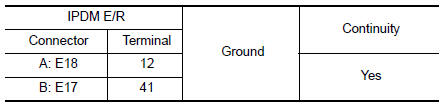
3. CHECK GROUND CIRCUIT
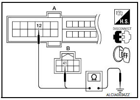
Check continuity between IPDM E/R harness connectors and ground.
PUSH-BUTTON IGNITION SWITCH POSITION INDICATOR
Description
The switch that changes the power supply position.
BCM maintains the power supply position status.
BCM changes the power supply position with the operation of the push-button ignition switch.
Component Function Check
1. CHECK FUNCTION
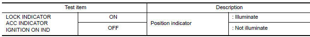
With CONSULT
- Check push-button ignition switch ("LOCK INDICATOR","ACC INDICATOR" and "IGNITION ON IND") in Active Test Mode with CONSULT.
Diagnosis Procedure
1. CHECK PUSH-BUTTON IGNITION SWITCH INPUT SIGNAL
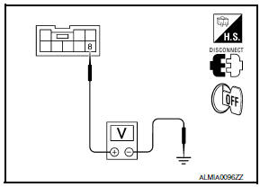
- Turn ignition switch OFF.
- Disconnect push-button ignition switch.
- Check voltage between push-button ignition switch harness connector and ground.
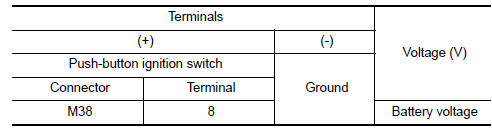
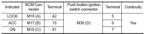
2. CHECK PUSH-BUTTON IGNITION SWITCH CIRCUIT
- Disconnect BCM and push-button ignition switch.
- Check continuity between BCM harness connector and pushbutton ignition switch harness connector.
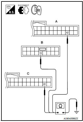
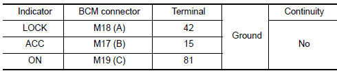
- Check continuity between BCM harness connector and ground.
3. CHECK PUSH-BUTTON IGNITION SWITCH
4. CHECK INTERMITTENT INCIDENT
Component Inspection
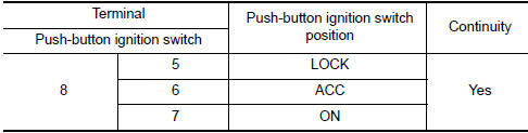
1. CHECK PUSH-BUTTON IGNITION SWITCH
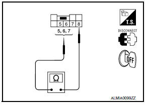
Check push-button ignition switch.
 B261A push-button ignition switch
Description
IPDM E/R transmits the push-button ignition switch status via CAN
communication to BCM. BCM receives
push-button ignition switch status by hardwire input. BCM compares the 2 signals
...

Other materials:
ECU diagnosis information
BCM (BODY CONTROL MODULE)
Reference Value
NOTE:
The Signal Tech II Tool (J-50190) can be used to perform the following
functions. Refer to the Signal Tech II
User Guide for additional information.
Activate and display TPMS transmitter IDs
Display tire pressure reported by the TPMS tran ...
Front fog lamp system
Wiring Diagram
...
Power supply routing circuit
Wiring Diagram -Battery Power Supply -
Wiring Diagram -Accessory Power Supply -
Wiring Diagram -Ignition Power Supply -
Fuse
If fuse is blown, be sure to eliminate cause of malfunction before
installing new fuse.
U ...
Nissan Maxima Owners Manual
- Illustrated table of contents
- Safety-Seats, seat belts and supplemental restraint system
- Instruments and controls
- Pre-driving checks and adjustments
- Monitor, climate, audio, phone and voice recognition systems
- Starting and driving
- In case of emergency
- Appearance and care
- Do-it-yourself
- Maintenance and schedules
- Technical and consumer information
Nissan Maxima Service and Repair Manual

0.0073