Nissan Maxima Service and Repair Manual: U0100 lost communication (ECM A)
DTC Logic
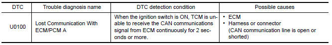
DTC DETECTION LOGIC
DTC CONFIRMATION PROCEDURE
1.PREPARATION BEFORE WORK
If another "DTC CONFIRMATION PROCEDURE" occurs just before, turn ignition switch OFF and wait for at least 10 seconds, then perform the next test.
2.PERFORM DTC CONFIRMATION PROCEDURE
- Start the engine and wait for at least 5 seconds.
- Check the first trip DTC.
Diagnosis Procedure
For the diagnosis procedure, refer to LAN-15, "Trouble Diagnosis Flow Chart".

 U1000 CAN comm circuit
Description
CAN (Controller Area Network) is a serial communication line for real time
application. It is an on-vehicle multiplex
communication line with high data communication speed and excelle ...
Other materials:
Precaution
PRECAUTIONS
Precaution for Supplemental Restraint System (SRS) "AIR BAG" and "SEAT
BELT
PRE-TENSIONER"
The Supplemental Restraint System such as "AIR BAG" and "SEAT BELT PRE-TENSIONER",
used along
with a front seat belt, helps to reduce the risk or severity of injury to ...
Sunroof does not operate properly
Diagnosis Procedure
1.CHECK SUNROOF MECHANISM
Check the following.
Operation malfunction caused by sunroof mechanism deformation,
pinched harness or other foreign materials
Operation malfunction and interference with other parts by poor
installation
2.CHECK SUNROOF MOTOR ASSEMBLY PO ...
Trunk lid opener
Wiring Diagram
...
Nissan Maxima Owners Manual
- Illustrated table of contents
- Safety-Seats, seat belts and supplemental restraint system
- Instruments and controls
- Pre-driving checks and adjustments
- Monitor, climate, audio, phone and voice recognition systems
- Starting and driving
- In case of emergency
- Appearance and care
- Do-it-yourself
- Maintenance and schedules
- Technical and consumer information
Nissan Maxima Service and Repair Manual

0.0057