Nissan Maxima Service and Repair Manual: Lifting switch (rear)
Description
Lifting switch (rear) is equipped to the power seat switch LH on the seat frame. The operation signal is inputted to the driver seat control unit when the lifting switch (rear) is operated.
Component Function Check
1. CHECK FUNCTION
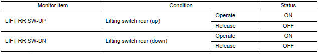
- Select "LIFT RR SW-UP", "LIFT RR SW-DN" in "DATA MONITOR mode with CONSULT.
- Check lifting switch (rear) signal under the following conditions.
Diagnosis Procedure
Regarding Wiring Diagram information, refer to ADP-150, "Wiring Diagram".
1. CHECK LIFTING SWITCH (REAR) SIGNAL
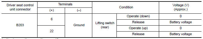
- Turn ignition switch OFF.
- Check voltage between driver seat control unit harness connector and ground
2. CHECK LIFTING SWITCH (REAR) CIRCUIT
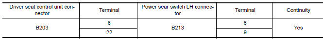
- Turn ignition switch OFF.
- Disconnect driver seat control unit and power seat switch LH.
- Check continuity between driver seat control unit harness connector and power seat switch LH harness connector.
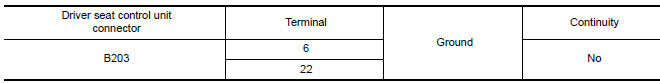
- Check continuity between driver seat control unit harness connector and ground.
3. CHECK DRIVER SEAT CONTROL UNIT OUTPUT
- Connect the driver seat control unit.
- Turn ignition switch ON.
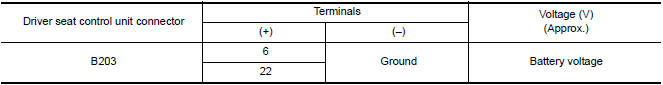
- Check voltage between driver seat control unit harness connector and ground.
4. CHECK LIFTING SWITCH (REAR)
Refer to ADP-57, "Component Inspection".
5. CHECK INTERMITTENT INCIDENT
Refer to GI-41, "Intermittent Incident".
Component Inspection
1. CHECK LIFTING SWITCH (REAR)
- Turn ignition switch OFF.
- Disconnect power seat switch LH.
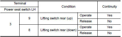
- Check continuity between power seat switch LH terminals.
 Lifting switch (front)
Description
Lifting switch (front) is equipped to the power seat switch LH on the seat
frame. The operation signal is input to the driver seat control unit when the
lifting switch (front) is oper ...
 Tilt switch
Description
ADP steering switch (tilt switch) is equipped to the steering column. The
operation signal is input to the automatic drive positioner control unit when
the tilt switch is operated.
C ...
Other materials:
P1212 TCS communication line
Description
This CAN communication line is used to control the smooth engine operation
during the TCS operation. Pulse
signals are exchanged between ECM and "ABS actuator and electric unit (control
unit)".
Be sure to erase the malfunction information such as DTC not only for "ABS
actuato ...
AMP on signal circuit
Description
When the audio system is turned on, a voltage signal is supplied from the AV
control unit to the BOSE speaker
amp. When this signal is received, the BOSE speaker amp. will turn on.
Diagnosis Procedure
1.CHECK AMP ON SIGNAL (BOSE SPEAKER AMP)
Turn audio system ON.
Check v ...
Intelligent key interlock function
INTELLIGENT KEY INTERLOCK FUNCTION : System
INTELLIGENT KEY INTERLOCK FUNCTION : System Description
OUTLINE
When unlocking doors by using Intelligent Key or door request switch (driver
side), seat slide and steering tilt move directly to the exit assist
function.
Other loads move to the ...
Nissan Maxima Owners Manual
- Illustrated table of contents
- Safety-Seats, seat belts and supplemental restraint system
- Instruments and controls
- Pre-driving checks and adjustments
- Monitor, climate, audio, phone and voice recognition systems
- Starting and driving
- In case of emergency
- Appearance and care
- Do-it-yourself
- Maintenance and schedules
- Technical and consumer information
Nissan Maxima Service and Repair Manual

0.0065