Nissan Maxima Service and Repair Manual: Lifting switch (front)
Description
Lifting switch (front) is equipped to the power seat switch LH on the seat frame. The operation signal is input to the driver seat control unit when the lifting switch (front) is operated.
Component Function Check
1. CHECK FUNCTION
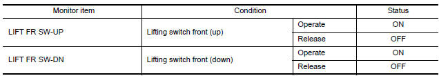
- Select "LIFT FR SW-UP", "LIFT FR SW-DN" in "DATA MONITOR" mode with CONSULT.
- Check lifting switch (front) signal under the following conditions.
Diagnosis Procedure
Regarding Wiring Diagram information, refer to ADP-150, "Wiring Diagram".
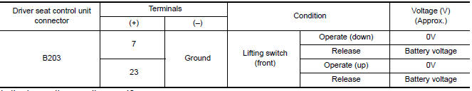
1. CHECK LIFTING SWITCH SIGNAL
- Turn ignition switch OFF.
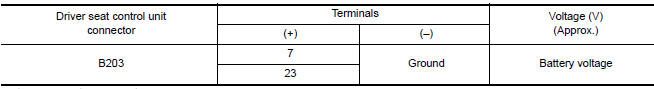
- Check voltage between driver seat control unit harness connector and ground.
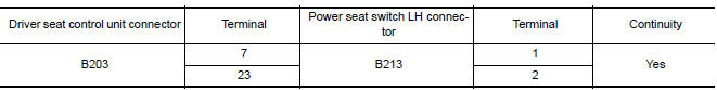
2. CHECK LIFTING SWITCH (FRONT) CIRCUIT
- Turn ignition switch OFF.
- Disconnect driver seat control unit and power seat switch LH.
- Check continuity between driver seat control unit harness connector and power seat switch LH harness connector.
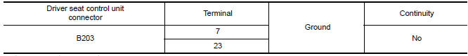
- Check continuity between driver seat contro unit harness connector and ground.
3. CHECK DRIVER SEAT CONTROL UNIT OUTPUT
- Connect the driver seat control unit.
- Turn ignition switch ON.
- Check voltage between driver seat control unit harness connector and ground.
4. CHECK LIFTING SWITCH (FRONT)
Refer to ADP-55, "Component Inspection".
5. CHECK INTERMITTENT INCIDENT
Refer to GI-41, "Intermittent Incident".
Component Inspection
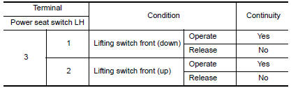
1. CHECK LIFTING SWITCH (FRONT)
- Turn ignition switch OFF.
- Disconnect power seat switch LH.
- Check continuity between power seat switch LH terminals.
 Reclining switch
Description
Reclining switch is equipped to the power seat switch LH on the seat frame.
The operation signal is input to the driver seat control unit when the
reclining switch is operated.
Compo ...
 Lifting switch (rear)
Description
Lifting switch (rear) is equipped to the power seat switch LH on the seat
frame. The operation signal is inputted to the driver seat control unit when
the lifting switch (rear) is ope ...
Other materials:
P0222, P0223 TP sensor
Description
Electric throttle control actuator consists of throttle control motor,
throttle position sensor, etc. The throttle position sensor responds to
the throttle valve movement.
The throttle position sensor has two sensors. These sensors are a
kind of potentiometer which transfor ...
Air cleaner
The air cleaner filter should not be cleaned and
reused. Replace it according to the maintenance
log shown in the "Maintenance and schedules"
section of this manual. When replacing the filter,
wipe the inside of the air cleaner filter housing
and the cover with a damp cloth.
To remove the ...
P1701 TCM
Description
When the power supply to the TCM is cut off, for example
because the battery is removed, and the self-diagnosis
memory function stops, a malfunction is detected.
NOTE:
Since "P1701" is indicated when replacing TCM, perform diagnosis after erasing
"Self Diagnostic Results".
DTC ...
Nissan Maxima Owners Manual
- Illustrated table of contents
- Safety-Seats, seat belts and supplemental restraint system
- Instruments and controls
- Pre-driving checks and adjustments
- Monitor, climate, audio, phone and voice recognition systems
- Starting and driving
- In case of emergency
- Appearance and care
- Do-it-yourself
- Maintenance and schedules
- Technical and consumer information
Nissan Maxima Service and Repair Manual

0.0053