Nissan Maxima Service and Repair Manual: Seatback thermal electric device
Description
Provides cooling and heat for the seatback.
Component Function Check
1.CHECK SEATBACK THERMAL ELECTRIC DEVICE FUNCTION
- Turn the climate controlled seat switch to the H (Heat) HI position and check that the seatback thermal electric device operates correctly.
- Turn the climate controlled seat switch to the C (Cool) HI position and check that the seatback thermal electric device operates correctly.
Diagnosis Procedure
Regarding Wiring Diagram information, refer to SE-44, "Wiring Diagram".
1.CHECK SEATBACK THERMAL ELECTRIC DEVICE
Perform thermal electric device component inspection for the seatback. Refer to SE-19, "Component Inspection (Thermal Electric Device)".
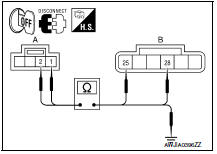
2.CHECK SEATBACK THERMAL ELECTRIC DEVICE CIRCUITS
- Turn ignition switch OFF.
- Disconnect seatback thermal electric device connector and climate controlled seat control unit connector B217.
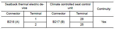
- Check continuity between seatback thermal electric device connector B218 (A) terminals 1, 2 and climate controlled seat control unit connector B217 (B) terminals 25, 28.
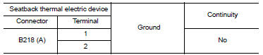
4. Check continuity between seatback thermal electric device connector B218 (A) terminals 1, 2 and ground.
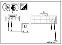
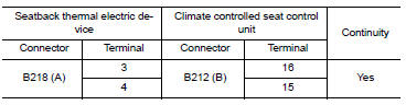
3.CHECK SEATBACK THERMAL ELECTRIC DEVICE SENSOR CIRCUITS
- Disconnect climate controlled seat control unit connector B212.
- Check continuity between seatback thermal electric device connector B218 (A) terminals 3, 4 and climate controlled seat control unit connector B212 (B) terminals 15, 16.
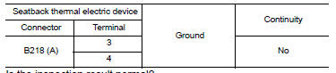
3. Check continuity between seatback thermal electric device connector B218 (A) terminals 3, 4 and ground.
Component Inspection (Thermal Electric Device)
1.CHECK THERMAL ELECTRIC DEVICE
- Turn ignition switch OFF.
- Disconnect thermal electric device connector.
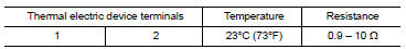
- Measure the resistance of the thermal electric device between terminals 1 and 2.
NOTE:
- The resistance value in the table below will change under any of the following conditions: air blowing across the thermal electric device
- changing the surrounding temperature of the thermal electric device
- measuring at other than 23C (73F)
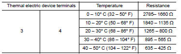
2.CHECK THERMAL ELECTRIC DEVICE SENSOR
Measure the resistance of the thermal electric device sensor between terminals 3 and 4.
 Seat cushion thermal electric device
Description
Provides cooling and heat for the seat cushion.
Component Function Check
1.CHECK SEAT CUSHION THERMAL ELECTRIC DEVICE FUNCTION
Turn the climate controlled seat switch to the H (Heat ...
 Climate controlled seat switch
Description
Provides inputs to the climate controlled seat control unit for climate
controlled seat operation.
Component Function Check
1.CHECK CLIMATE CONTROLLED SEAT SWITCH FUNCTION
Turn the c ...
Other materials:
Switch operation
Type A (if so equipped)
The windshield wiper and washer operates when
the ignition switch is placed in the ON position.
Push the lever down to operate the wiper at the
following speed:
Intermittent (INT) or (AUTO) - intermittent
operation can be adjusted by turning the
knob A .
L ...
Installing front license plate
Use the following steps to mount the front license
plate:
1. Make holes on the plastic finisher at the
location mark (small dimple) using a 5 mm
(0.20 in) drill. Apply light pressure to the drill.
Install the license plate holder using the two
screws provided with the holder.
2. Mount ...
Rear combination lamp
Disassembly and Assembly
Rear combination lamp
Rear side marker lamp socket
Rear side marker lamp bulb
Rear turn signal lamp socket
Rear turn signal lamp bulb
Back-up lamp socket
Back-up lamp bulb
DISASSEMBLY
Rotate the rear side marker lamp socket counterclockwise and ...
Nissan Maxima Owners Manual
- Illustrated table of contents
- Safety-Seats, seat belts and supplemental restraint system
- Instruments and controls
- Pre-driving checks and adjustments
- Monitor, climate, audio, phone and voice recognition systems
- Starting and driving
- In case of emergency
- Appearance and care
- Do-it-yourself
- Maintenance and schedules
- Technical and consumer information
Nissan Maxima Service and Repair Manual

0.009