Nissan Maxima Service and Repair Manual: Key slot
Diagnosis Procedure
Regarding Wiring Diagram information, refer to SEC-147, "Wiring Diagram" or SEC-128, "Wiring Diagram".
1.CHECK KEY SLOT POWER SUPPLY CIRCUIT
-
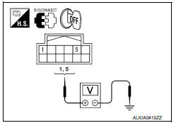
Turn ignition switch OFF.
-
Disconnect key slot connector.
-
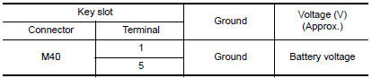
Check voltage between slot harness connector M40 terminal 1, 5 and ground.
2.CHECK KEY SLOT GROUND CIRCUIT
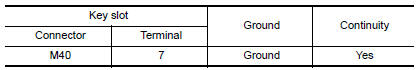
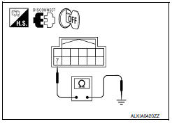
Check continuity between key slot harness connector M40 terminal 7 and ground.
3.CHECK INTERMITTENT INCIDENT
Refer to GI-41, "Intermittent Incident".
Inspection End.
 IPDM E/R (intelligent power distribution module engine room)
IPDM E/R (INTELLIGENT POWER DISTRIBUTION MODULE ENGINE
ROOM) : Diagnosis
Procedure
Regarding Wiring Diagram information, refer to PCS-28,
"Wiring Diagram".
1. CHECK FUSES AND FUSIBLE LINK
Che ...
 Key slot illumination
Description
Blinks when Intelligent Key insertion is required.
Component Function Check
1.CHECK FUNCTION
With CONSULT
Check key slot illumination ("KEY SLOT ILLUMI") Active
Test mode.
Diagnos ...
Other materials:
Instrument panel assembly
Exploded View
Center speaker grille (if equipped)
Tweeter speaker grille (LH)
Front defroster grille (LH)
Instrument panel
Instrument side finisher (LH)
Lower knee protector (LH)
Instrument lower panel (LH)
Fuse block cover
Steering column lower cover (power tilt)
Ste ...
Rear door finisher
Exploded View
Rear door finisher
Step lamp
Armrest finisher
Rear power window switch finisher
Inside release handle escutcheon
Inside release handle
Flat head screws
Screw Clip
Pawl
Front
Removal and Installation
CAUTION: Wrap the tip of a suitab ...
Door switch
Description
Detects door open/close condition.
Component Function Check
1.CHECK FUNCTION
With CONSULT
Check door switches DOOR SW-DR, DOOR SW-AS in Data Monitor mode with CONSULT.
Diagnosis Procedure
1.CHECK DOOR SWITCH INPUT SIGNAL
Turn ignition switch OFF.
Check signal between B ...
Nissan Maxima Owners Manual
- Illustrated table of contents
- Safety-Seats, seat belts and supplemental restraint system
- Instruments and controls
- Pre-driving checks and adjustments
- Monitor, climate, audio, phone and voice recognition systems
- Starting and driving
- In case of emergency
- Appearance and care
- Do-it-yourself
- Maintenance and schedules
- Technical and consumer information
Nissan Maxima Service and Repair Manual

0.0076