Nissan Maxima Service and Repair Manual: SRS air bag system
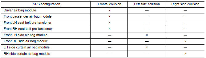
SRS Configuration
The air bag deploys if the air bag diagnosis sensor unit is activated while
the ignition switch is in the ON or
START position.
The collision modes
for which supplemental restraint systems are activated are different among the
SRS systems.
For example, the driver air bag module, front passenger air bag
module and front seat belt pre-tensioners
are activated in a frontal
collision but not in a side collision.
SRS configurations for some collision
modes are as follows:
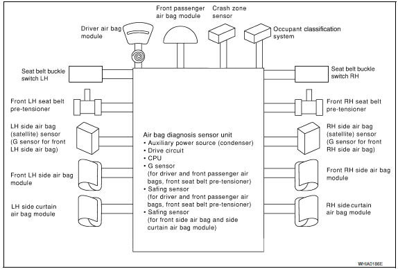
SRS Component Parts Location
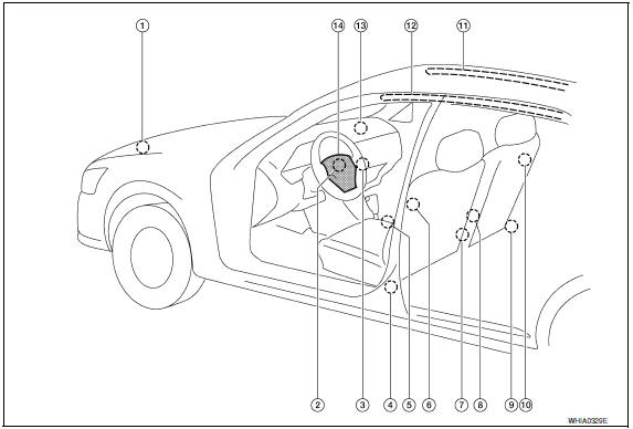
- Crash zone sensor
- Spiral cable
- Front passenger air bag off indicator
- Front LH seatbelt pre-tensioner
LH side air bag (satellite) sensor - Air bag diagnosis sensor unit
- Front LH side air bag module
- Seat belt buckle switch (LH)
Seat belt buckle switch (RH) - Occupant classification system
control unit and sensor mat - Front RH seatbelt pre-tensioner
RH side air bag (satellite) sensor - Front RH side air bag module
- RH side curtain air bag module
- LH side curtain air bag module
- Front passenger air bag module
- Driver air bag module
Driver Air Bag Module
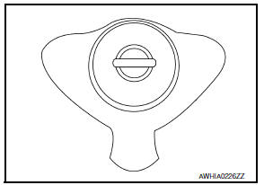
The driver air bag module is dual stage and located in the steering
wheel
assembly. It operates with the SRS system in a frontal collision
exceeding a
specified level.
Front Passenger Air Bag Module
The front passenger air bag module is located behind the instrument
panel
assembly. It operates with the SRS system in a frontal collision
exceeding a
specified level. Refer to SRC-10, "Occupant Classification
System (OCS)" for
more information.
Front Side Air Bag
Front side air bag modules are built into the front seatback assemblies.
Vehicles with side air bags are equipped with labels as shown.
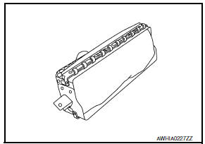
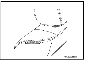
Side Curtain Air Bag
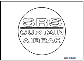
Side curtain air bag modules are located above the vehicle headlining.
Vehicles with side curtain air bags are equipped with labels as
shown.
Front Seat Belt Pre-tensioner
The seat belt pre-tensioner system with load limiter is installed for
both
the driver's seat and the front passenger's seat. It operates
simultaneously
with the SRS air bag system in the event of a frontal
collision with an
impact exceeding a specified level.
When the frontal collision with an impact
exceeding a specified level
occurs, seat belt slack resulting from clothing
or other factors is
immediately taken up by the pre-tensioner. Vehicle
passengers are
securely restrained.
When passengers in a vehicle are
thrown forward in a collision and
the restraining force of the seat belt
exceeds a specified level, the
load limiter permits the specified extension
of the seat belt by the
twisting of the ELR shaft, and a relaxation of the
chest-area seat belt
web tension while maintaining force.
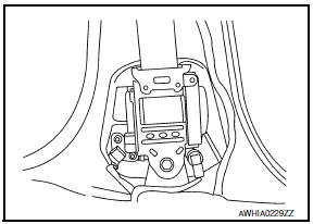
SRS Component Connectors
DIRECT CONNECT
The following SRS components use direct-connect style harness connectors.
- Driver front air bag module
- Passenger front air bag module
- LH side curtain air bag module
- RH side curtain air bag module
- Front LH seat belt pre-tensioner
- Front RH seat belt pre-tensioner
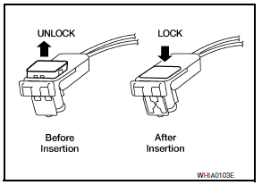
Always pull up to release locking tab prior to removing connector from SRS
component.
Always push down to lock locking tab after installing connector to
SRS component. When locked, the locking tab is level with the connector
housing.
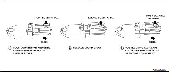
SLIDE DOUBLE LOCKING
- A new style slide double locking type connector is used on certain
systems and components, especially
those related to airbag control systems. - The slide double locking type connectors help prevent incomplete locking and accidental looseness or disconnection.
- The slide double locking type connectors are disconnected by
pushing or pulling the slider. Refer to the figure
below.
CAUTION:
- Do not pull the harness or wires when disconnecting the connector.

 Occupant classification system
System Diagram
Occupant Classification System (OCS)
The occupant classification system (OCS) identifies if a child or child
seat is present in the front passenger seat. The OCS receives input ...
Other materials:
Precaution
Precaution for Supplemental Restraint System (SRS) "AIR BAG" and
"SEAT BELT PRE-TENSIONER"
The Supplemental Restraint System such as "AIR BAG" and "SEAT BELT
PRE-TENSIONER", used along with a front seat belt, helps to reduce the risk
or severity of injury to the driver and front passenger for ...
Back-up lamp
Wiring Diagram
...
Stop lamp
Wiring Diagram
...
Nissan Maxima Owners Manual
- Illustrated table of contents
- Safety-Seats, seat belts and supplemental restraint system
- Instruments and controls
- Pre-driving checks and adjustments
- Monitor, climate, audio, phone and voice recognition systems
- Starting and driving
- In case of emergency
- Appearance and care
- Do-it-yourself
- Maintenance and schedules
- Technical and consumer information
Nissan Maxima Service and Repair Manual

0.0057