Nissan Maxima Service and Repair Manual: Occupant classification system
System Diagram
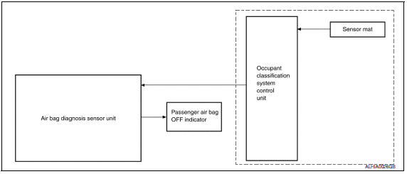
Occupant Classification System (OCS)
The occupant classification system (OCS) identifies if a child or child
seat is present in the front passenger seat. The OCS receives inputs
from the
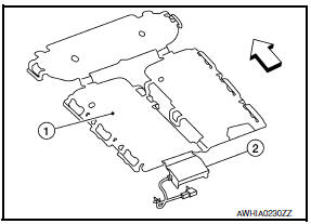
occupant classification sensor mat (1) which is located
inside the passenger
seat cushion assembly. Depending on classification
of the passenger, the OCS
control unit (2) sends a signal to
the air bag diagnosis sensor unit. The air
bag diagnosis sensor unit
uses this signal and the seat belt buckle switch RH
signal to determine
deployment or non-deployment of the front passenger air
bag
module in the event of a collision. Depending on the signals
received,
the air bag diagnosis sensor unit can disable the front passenger
air bag
module completely.
NOTE:
In case of
customer concern, CONSULT can be used to confirm the front passenger air bag
status (readiness).
Front Passenger Air Bag Status Conditions
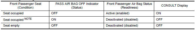
NOTE:
Passenger does not meet Occupant Classification
System specifications for passenger air bag activation.
 SRS air bag system
SRS Configuration
The air bag deploys if the air bag diagnosis sensor unit is activated while
the ignition switch is in the ON orSTART position.The collision modes
for which supplemental restra ...
 Passenger seat belt warning system
System Diagram
System Description
The seat belt warning lamp (1) will remind the driver if the driver or
front passenger seat belt should be buckled. The system works inconjunction
with the o ...
Other materials:
Warning lamp
Description
Warning lamp is built in combination meter.
Intelligent Key system malfunction is reported
to the driver by the warning lamp illumination.
Component Function Check
1.CHECK FUNCTION
Perform "INDICATOR" in the "Active Test" mode
with CON ...
HVAC branch line circuit
Diagnosis Procedure
1.CHECK CONNECTOR
Turn the ignition switch OFF.
Disconnect the battery cable from the negative terminal.
Check the terminals and connectors of the A/C auto amp. for
damage, bend and loose connection (unit
side and connector side).
2.CHECK HARNESS FOR OPEN CIRCUI ...
Main line between HVAC and A-bag circuit
Diagnosis Procedure
1.CHECK HARNESS CONTINUITY (OPEN CIRCUIT)
Turn the ignition switch OFF.
Disconnect the battery cable from the negative terminal.
Disconnect the following harness connectors.
A/C auto amp.
Harness connectors M1 and E30
Check the continuity between the A/C au ...
Nissan Maxima Owners Manual
- Illustrated table of contents
- Safety-Seats, seat belts and supplemental restraint system
- Instruments and controls
- Pre-driving checks and adjustments
- Monitor, climate, audio, phone and voice recognition systems
- Starting and driving
- In case of emergency
- Appearance and care
- Do-it-yourself
- Maintenance and schedules
- Technical and consumer information
Nissan Maxima Service and Repair Manual

0.0061