Nissan Maxima Service and Repair Manual: System description
STARTING SYSTEM
System Diagram
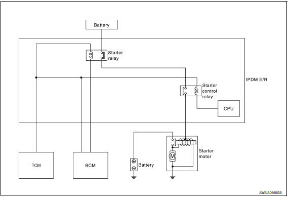
System Description
The starter motor plunger closes and provides a closed circuit between the battery and the starter motor. The starter motor is grounded to the cylinder block. With power and ground supplied, the starter motor operates.
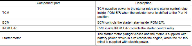
Component Description
 Basic inspection
DIAGNOSIS AND REPAIR WORKFLOW
Work Flow (With GR8-1200 NI)
STARTING SYSTEM DIAGNOSIS WITH GR8-1200 NI
To test the starting system, use the following special service tool:
GR8-1200 NI Mult ...

Other materials:
Precaution
PRECAUTIONS
Precaution for Supplemental Restraint System (SRS) "AIR BAG" and
"SEAT BELT PRE-TENSIONER
The Supplemental Restraint System such as "AIR BAG" and "SEAT BELT
PRE-TENSIONER", used along with a front seat belt, helps to reduce the risk
or severity of injury to the driver and front p ...
Power seat for passenger side
Wiring Diagram
...
Power window and door lock/unlock switch RH
Reference Value
TERMINAL LAYOUT
PHYSICAL VALUES
POWER WINDOW AND DOOR LOCK/UNLOCK SWITCH RH
Fail Safe
FAIL-SAFE CONTROL
Switches to fail-safe control when malfunction is detected in encoder signal
that detects up/down speed and
direction of door glass. Switches to fail-safe con ...
Nissan Maxima Owners Manual
- Illustrated table of contents
- Safety-Seats, seat belts and supplemental restraint system
- Instruments and controls
- Pre-driving checks and adjustments
- Monitor, climate, audio, phone and voice recognition systems
- Starting and driving
- In case of emergency
- Appearance and care
- Do-it-yourself
- Maintenance and schedules
- Technical and consumer information
Nissan Maxima Service and Repair Manual

0.0058