Nissan Maxima Service and Repair Manual: Basic inspection
DIAGNOSIS AND REPAIR WORKFLOW
Work Flow (With GR8-1200 NI)
STARTING SYSTEM DIAGNOSIS WITH GR8-1200 NI
To test the starting system, use the following special service tool:
- GR8-1200 NI Multitasking battery and electrical diagnostic station
NOTE: Refer to the diagnostic station Instruction Manual for proper starting system diagnosis procedures
OVERALL SEQUENCE
DETAILED FLOW
NOTE: To ensure a complete and thorough diagnosis, the battery, starter motor and generator test segments must be done as a set from start to finish.
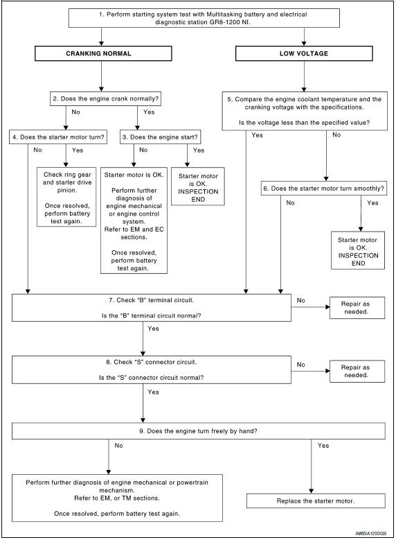
1.DIAGNOSIS WITH MULTITASKING BATTERY AND ELECTRICAL DIAGNOSTIC STATION GR8-1200 NI
Perform the starting system test with Multitasking battery and electrical diagnostic station GR8-1200 NI. For details and operating instructions, refer to diagnostic station Instruction Manual.
2.CRANKING CHECK
Check that the starter motor operates properly.
3.ENGINE START CHECK
Check that the engine starts.
4.STARTER MOTOR ACTIVATION
Check that the starter motor operates.
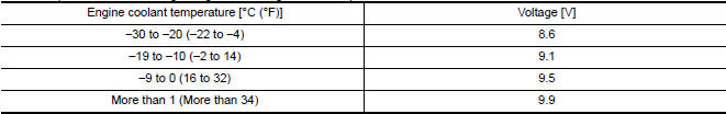
5.COMPARISON BETWEEN ENGINE COOLANT AND CRANKING VOLTAGE
Compare the engine coolant temperature and verify the cranking voltage is within specifications.
Minimum Specification of Cranking Voltage Referencing Coolant Temperature
6.STARTER OPERATION
Check the starter operation.
7."B" TERMINAL CIRCUIT INSPECTION
Check "B" terminal circuit.
8."S" CONNECTOR CIRCUIT INSPECTION
Check "S" connector circuit.
9.ENGINE ROTATION STATUS
Check that the engine can be rotated by hand.
Work Flow (Without GR8-1200 NI)
OVERALL SEQUENCE
DETAILED FLOW
NOTE: If any malfunction is found, immediately disconnect the battery cable from the negative terminal.
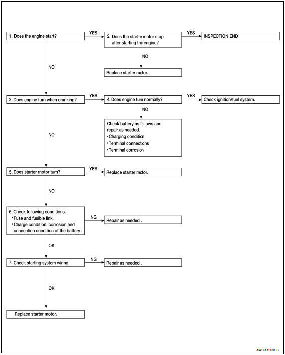
1.CHECK ENGINE START
Crank the engine and check that the engine starts.
2.CHECK THAT THE STARTER MOTOR STOPS
Check that the starter motor stops after starting the engine.
3.CHECK THAT THE ENGINE TURNS WHEN CRANKING
Check that the engine turns when cranking.
4.CHECK THE ENGINE SPEED WHEN CRANKING
Check that the engine speed is not low when cranking.
5.CHECK STARTER MOTOR ACTIVATION
Check that the starter motor runs at cranking.
6.CHECK POWER SUPPLY CIRCUIT
Check the following conditions:
- Fuse and fusible link
- Charge condition, corrosion and connection of the battery
7.CHECK STARTING SYSTEM WIRING
Check the following:
- "B" terminal circuit. Refer to STR-9, "Diagnosis Procedure".
- "S" terminal circuit
 Starting system
...
 System description
STARTING SYSTEM
System Diagram
System Description
The starter motor plunger closes and provides a closed circuit between the
battery and the starter motor. The starter motor is grounded to the ...
Other materials:
Cooling and/or dehumidified heating
(AUTO)
This mode may be used all year round as the
system automatically works to keep a constant
temperature. Air flow distribution and fan speed
are also controlled automatically.
1. Press the AUTO button on.
2. Turn the temperature control dial to the left
or right to set the desired temperatur ...
Diagnosis and repair workflow
Work Flow
OVERALL SEQUENCE
DETAILED FLOW
1. GET INFORMATION FOR SYMPTOM
Get the detailed information from the customer about the symptom (the
condition and the environment when
the incident/malfunction occurred).
2. CHECK DTC
Check DTC.
Perform the following procedure if DTC is ...
Combination meter
Removal and Installation
REMOVAL
Disconnect the negative battery terminal. Refer
to PG-67, "Removal and Installation (Battery)".
Remove the cluster lid A. Refer to IP-16,
"Removal and Installation".
Remove the combination meter screws (A) using
powe ...
Nissan Maxima Owners Manual
- Illustrated table of contents
- Safety-Seats, seat belts and supplemental restraint system
- Instruments and controls
- Pre-driving checks and adjustments
- Monitor, climate, audio, phone and voice recognition systems
- Starting and driving
- In case of emergency
- Appearance and care
- Do-it-yourself
- Maintenance and schedules
- Technical and consumer information
Nissan Maxima Service and Repair Manual

0.0066