Nissan Maxima Service and Repair Manual: Compressor control function
Description
PRINCIPLE OF OPERATION
A/C compressor is not activated.
Functional circuit diagram
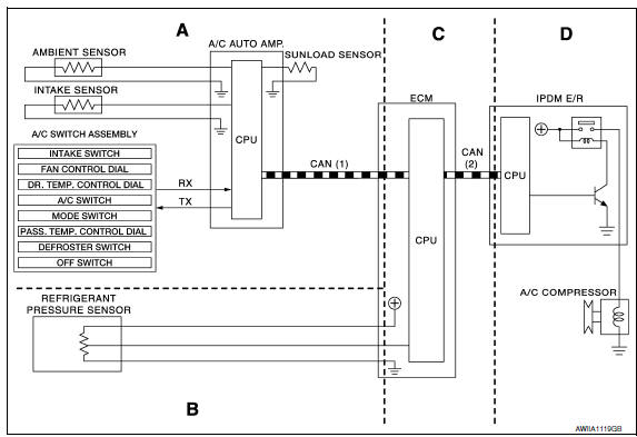
CAN (1): A/C switch signal
: Blower fan motor switch signal
CAN (2): A/C compressor request signal
RX: A/C switch signal
: Fan ON signal
: Defroster signal
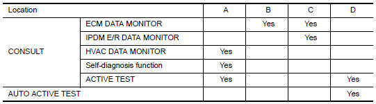
Functional initial inspection chart
Fail-Safe
FAIL-SAFE FUNCTION
- If a communication error exists between the A/C auto amp., the AV control unit and the A/C and AV switch assembly for 30 seconds or longer, air conditioner is controlled under the following conditions:
Compressor: ON
Air outlet: AUTO
Air inlet: FRE (  )
)
Blower fan speed: AUTO
Set temperature: Setting before communication error occurs

 Automatic air conditioner system
System Diagram
CONTROL SYSTEM
The control system consists of input sensors, switches, the A/C auto amp.
(microcomputer) and outputs. The
relationship of these components is as shown in the figure ...
Other materials:
P1078, P1084 EVT control position sensor
Description
Exhaust valve timing control position sensor detects the concave
groove of the exhaust camshaft rear end.
This sensor signal is used for sensing a position of the exhaust camshaft.
This sensor uses a Hall IC.
Based on the position of the exhaust camshaft, ECM controls
e ...
Air conditioner system refrigerant and oil recommendations
The air conditioner system in your NISSAN
vehicle must be charged with the refrigerant
HFC-134a (R-134a) and Genuine
NISSAN A/C System Oil Type ND-OIL8 or
the exact equivalents.
CAUTION
The use of any other refrigerant or oil may
cause severe damage to the air conditioning
system and may req ...
Mechanical key
The Intelligent Key contains the mechanical key,
which can be used in case of a discharged battery.
To remove the mechanical key, release the lock
knob on the back of the Intelligent Key.
To install the mechanical key, firmly insert it into
the Intelligent Key until the lock knob return ...
Nissan Maxima Owners Manual
- Illustrated table of contents
- Safety-Seats, seat belts and supplemental restraint system
- Instruments and controls
- Pre-driving checks and adjustments
- Monitor, climate, audio, phone and voice recognition systems
- Starting and driving
- In case of emergency
- Appearance and care
- Do-it-yourself
- Maintenance and schedules
- Technical and consumer information
Nissan Maxima Service and Repair Manual

0.0065