Nissan Maxima Service and Repair Manual: Unit removal and installation
Rear suspension assembly
Exploded View
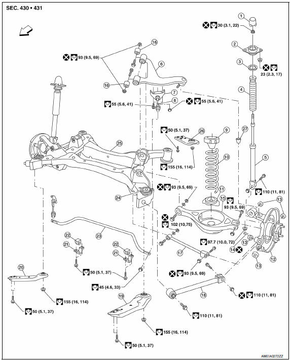
- Rear shock absorber cap
- Strut mount insulator
- Shock absorber mount seal
- Rear suspension bound bumper
- Rear shock absorber
- Rear suspension arm
- Connecting rod mount bracket
- Rear stabilizer connecting rod
- Rear spring upper rubber seat
- Rear suspension spring
- Rear spring lower rubber seat
- Rear axle housing
- Bushing
- Upper ball joint cotter pin
- Rear lower link
- Arm bushing stopper
- Front lower link
- Radius rod
- Rear suspension member stay (Front LH)
- Rear suspension member stay (Front RH)
- Rear stabilizer clamp
- Rear stabilizer bushing
- Rear stabilizer
- Rear suspension mount insulator
- Rear suspension member
- Rear suspension member stay (Rear LH)
- Ball seat
 Front
Front
Removal and Installation
Removal
CAUTION: Before removing the rear suspension member, remove each rear wheel sensor from each rear axle housing. Failure to do so may result in damage to the sensor wires and the sensor becoming inoperative.
- Remove the center exhaust tube with muffler(s). Refer to EX-5, "Removal and Installation".
- Remove each brake caliper using power tools and reposition each brake caliper aside with wire. Refer to BR-36, "Removal and Installation of Brake Caliper and Rotor".
- Leave each brake hydraulic hose connected to each brake caliper.
- Do not depress the brake pedal, or the caliper pistons will pop out.
- Do not pull or twist the brake hydraulic hoses.
- Remove each brake rotor.
- Disconnect each parking brake cable from each rear axle housing. Refer to PB-6, "Exploded View".
- Remove each rear wheel sensor. Refer to BRC-103, "Removal and Installation - Rear Wheel Sensor".
- Remove each lower shock absorber nut and bolt using power tools.
- Remove each rear lower link. Refer to RSU-8, "Removal and Installation".
- Remove each upper ball joint nut and cotter pin. Refer to RSU-15, "Exploded View".
- Remove each radius rod. Refer to RSU-12, "Removal and Installation".
- Remove each front lower link. Refer to RSU-11, "Removal and Installation".
- Remove each rear axle housing using Tool
Tool number : HT72520000 (J-25730-B)
CAUTION:
- Do not damage ball joint when removing.
- While using Tool, temporarily tighten the nut so as not to damage screw threads.
- Remove the rear stabilizer. Refer to RSU-13, "Removal and Installation".
- Disconnect the member harness.
- Support rear suspension member using a suitable jack.
- Remove the rear suspension member nuts and the rear suspension member stay bolts using power tools.
- Lower the jack to remove the rear suspension member.
- If necessary, remove each rear suspension arm. Refer to RSU-14, "Removal and Installation".
Installation
Installation is in the reverse order of removal.
CAUTION:
- Do not reuse the front lower link nuts.
- Do not reuse the radius rod nuts at the rear axle housing.
- Do not reuse the upper ball joint cotter pin.
- Do not reuse the rear lower link nuts at the rear suspension member.
- Check wheel alignment. Adjust as necessary. Refer to RSU-6, "Inspection and Adjustment".
- Install member stays in correct position.
NOTE: Member stays are directional.
 Suspension ARM
Removal and Installation
Removal
Remove the rear suspension member. Refer to RSU-16, "Removal and
Installation".
Remove the connecting rod mount bracket nut and bolt from the rear
suspens ...
 Service data and specifications (SDS)
General Specification (Rear)
Wheel Alignment (Unladen*1)
*1: Fuel, engine coolant, and lubricants are full. Spare tire, jack, hand
tools, and mats are in designated positions. *2: 18" tire ...
Other materials:
Power generation voltage variable control system operation
inspection
Diagnosis Procedure
CAUTION:
When performing this inspection, always use a charged battery that has completed
the battery inspection.
(When the charging rate of the battery is low, the response speed of the voltage
change will
become slow. This can cause an incorrect inspection.)
1.CHEC ...
Precaution
Precaution for Supplemental Restraint System (SRS) "AIR BAG" and
"SEAT BELT PRE-TENSIONER"
The Supplemental Restraint System such as "AIR BAG" and "SEAT BELT
PRE-TENSIONER", used along with a front seat belt, helps to reduce the risk
or severity of injury to the driver and front passenger for ...
Rear stabilizer
Removal and Installation
Removal
Remove each rear stabilizer connecting rod nut using power tools.
Disconnect the rear stabilizer from each rear stabilizer
connecting rod.
Remove each rear stabilizer clamp bolt using power tools.
Remove the rear stabilizer.
If necessary, remove each ...
Nissan Maxima Owners Manual
- Illustrated table of contents
- Safety-Seats, seat belts and supplemental restraint system
- Instruments and controls
- Pre-driving checks and adjustments
- Monitor, climate, audio, phone and voice recognition systems
- Starting and driving
- In case of emergency
- Appearance and care
- Do-it-yourself
- Maintenance and schedules
- Technical and consumer information
Nissan Maxima Service and Repair Manual

0.0051