Nissan Maxima Service and Repair Manual: C1111 pump motor
Description
PUMP
The pump returns the brake fluid stored in the reservoir to the master cylinder by reducing the pressure.
MOTOR
The motor drives the pump according to the signals transmitted by the ABS actuator and electric unit (control unit).
DTC Logic
DTC DETECTION LOGIC
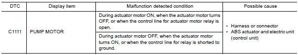
DTC CONFIRMATION PROCEDURE
1.CHECK SELF-DIAGNOSIS RESULTS
Check the self-diagnosis results.

Diagnosis Procedure
Regarding Wiring Diagram information
1.CONNECTOR INSPECTION
- Turn ignition switch OFF.
- Disconnect ABS actuator and electric unit (control unit) connector.
- Check terminals for deformation, disconnection, looseness, and so on. If any malfunction is found, repair or replace terminals.
- Reconnect connector and perform self-diagnosis.
2. CHECK ABS MOTOR AND MOTOR RELAY POWER SUPPLY CIRCUIT
- Turn ignition switch OFF.
- Disconnect ABS actuator and electric unit (control unit) connector.
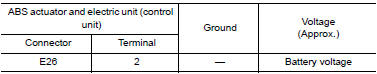
- Check voltage between ABS actuator and electric unit (control unit) connector E26 terminal 2 and ground.
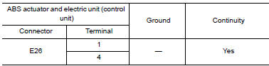
3. CHECK ABS ACTUATOR AND ELECTRIC UNIT (CONTROL UNIT) GROUND CIRCUIT
Check continuity between ABS actuator and electric unit (control unit) connector E26 terminals 1, 4 and ground.
Component Inspection
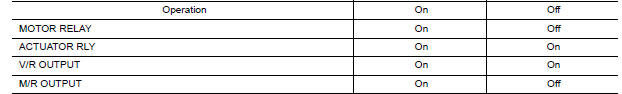
1.CHECK ACTIVE TEST
- On "ACTIVE TEST", select "ABS MOTOR".
- Touch "On" and "Off" on screen. Make sure motor relay, actuator relay, V/R output and M/R output operate as shown in table below.
Special Repair Requirement
1.ADJUSTMENT OF STEERING ANGLE SENSOR NEUTRAL POSITION
Always perform the neutral position adjustment for the steering angle sensor, when replacing the ABS actuator and electric unit (control unit).
 C1110, C1153, C1170 ABS actuator and electric unit (control unit)
DTC Logic
DTC DETECTION LOGIC
DTC CONFIRMATION PROCEDURE
1.CHECK SELF-DIAGNOSIS RESULTS
Check the self-diagnosis results.
Diagnosis Procedure
1.REPLACE ABS ACTUATOR AND ELECTRIC UNIT (CO ...
 C1114 main relay
Description
Activates or deactivates each solenoid valve according to the signals
transmitted by the ABS actuator and
electric unit (control unit).
DTC Logic
DTC DETECTION LOGIC
DTC CONFIR ...
Other materials:
Lock-up and select control system
System Diagram
System Description
The torque converter clutch piston in the torque converter is
engaged to eliminate torque converter slip to
increase power transmission efficiency.
The torque converter clutch control valve operation is controlled
by the torque converte ...
Door lock function
DOOR LOCK AND UNLOCK SWITCH
DOOR LOCK AND UNLOCK SWITCH : System Diagram
DOOR LOCK AND UNLOCK SWITCH : System Description
DOOR LOCK FUNCTION
Functions Available by Operating the Door Lock and Unlock Switches on
Driver Door and Passenger Door
Interlocked with the locking operation o ...
Tweeter
Description
The audio unit sends audio signals to the BOSE speaker amp. The BOSE speaker
amp. amplifies the audio signals before sending them to the tweeters using
the audio signal circuits.
Diagnosis Procedure
1.CONNECTOR CHECK
Check the audio unit, BOSE speaker amp. and speaker connectors ...
Nissan Maxima Owners Manual
- Illustrated table of contents
- Safety-Seats, seat belts and supplemental restraint system
- Instruments and controls
- Pre-driving checks and adjustments
- Monitor, climate, audio, phone and voice recognition systems
- Starting and driving
- In case of emergency
- Appearance and care
- Do-it-yourself
- Maintenance and schedules
- Technical and consumer information
Nissan Maxima Service and Repair Manual

0.0056