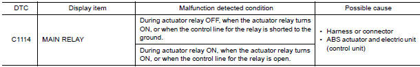
Nissan Maxima Service and Repair Manual: C1114 main relay
Description
Activates or deactivates each solenoid valve according to the signals transmitted by the ABS actuator and electric unit (control unit).
DTC Logic
DTC DETECTION LOGIC
DTC CONFIRMATION PROCEDURE
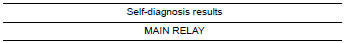
1.CHECK SELF-DIAGNOSIS RESULTS
Check the self-diagnosis results.
Diagnosis Procedure
1.CONNECTOR INSPECTION
- Turn ignition switch OFF.
- Disconnect ABS actuator and electric unit (control unit) connector.
- Check terminals for deformation, disconnection, looseness, and so on. If any malfunction is found, repair or replace terminals.
- Reconnect connector and perform self-diagnosis
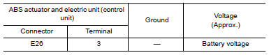
2.CHECK SOLENOID AND ACTUATOR RELAY POWER SUPPLY CIRCUIT
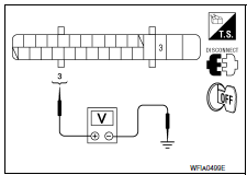
- Turn ignition switch OFF.
- Disconnect ABS actuator and electric unit (control unit) connector.
- Check voltage between ABS actuator and electric unit (control unit) connector E26 terminal 3 and ground.
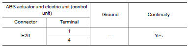
3. CHECK SOLENOID AND ACTUATOR RELAY GROUND CIRCUIT
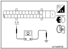
Check continuity between ABS actuator and electric unit (control unit) connector E26 terminals 1, 4 and ground.
Component Inspection
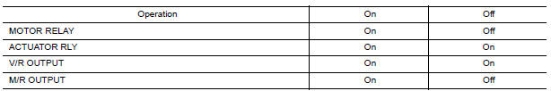
1.CHECK ACTIVE TEST
- On "ACTIVE TEST", select "ABS MOTOR".
- Touch "On" and "Off" on screen. Make sure motor relay, actuator relay, V/R output and M/R output operate as shown in table below.
Special Repair Requirement
1.ADJUSTMENT OF STEERING ANGLE SENSOR NEUTRAL POSITION
Always perform the neutral position adjustment for the steering angle sensor, when replacing the ABS actuator and electric unit (control unit).
 C1111 pump motor
Description
PUMP
The pump returns the brake fluid stored in the reservoir to the master
cylinder by reducing the pressure.
MOTOR
The motor drives the pump according to the signals transmitted by ...
 C1115 ABS sensor [abnormal signal]
Description
When the sensor rotor rotates, the magnetic field changes. It converts the
magnetic field changes to current
signals (rectangular wave) and transmits them to the ABS actuator and elec ...
Other materials:
Blower motor
Description
COMPONENT DESCRIPTION
Brush-less Motor
The blower motor utilizes a brush-less motor with a rotating magnet.
Quietness is improved over previous motors where the brush was
the point of contact and the coil rotated.
Blower Motor Circuit
Component Function Check
1.CHECK OP ...
Emission control information label
The emission control information label is attached
to the underside of the hood as shown.
Tire and loading information label
The cold tire pressure is shown on the Tire and
Loading Information label. The label is located as
shown.
Air conditioner specification label
The air condit ...
Control unit
Removal and Installation
A/C AND AV SWITCH ASSEMBLY
Removal and Installation
The A/C and AV switch assembly is located in cluster lid C.
Refer to AV-481, "Removal and Installation" (BOSE W/COLOR
DISPLAY).
Refer to AV-652, "Removal and Installation" (BOSE W/COLOR DISPL ...
Nissan Maxima Owners Manual
- Illustrated table of contents
- Safety-Seats, seat belts and supplemental restraint system
- Instruments and controls
- Pre-driving checks and adjustments
- Monitor, climate, audio, phone and voice recognition systems
- Starting and driving
- In case of emergency
- Appearance and care
- Do-it-yourself
- Maintenance and schedules
- Technical and consumer information
Nissan Maxima Service and Repair Manual

0.0056