Nissan Maxima Service and Repair Manual: Magnet clutch
Description
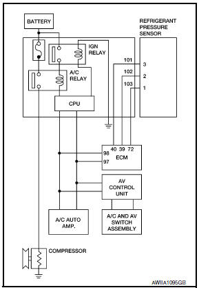
SYSTEM DESCRIPTION
A/C auto amp. controls A/C compressor operation by ambient temperature and signal from ECM.
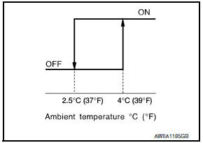
Low Temperature Protection Control A/C auto amp. will turn the A/C compressor ON or OFF as determined by a signal detected by ambient sensor.
When ambient temperature is greater than 4C (39F), the A/C compressor turns ON. The A/C compressor turns OFF when ambient temperature is less than 2.5C (37F).
Component Function Check
1.FUNCTION INSPECTIONS
- Press AUTO switch. AUTO is indicated on the display.
- Press the A/C switch.
- Check that the indicator of the A/C switch turns on. Check visually and by sound that the compressor is operating. (The discharge air temperature or fan speed varies depending on the ambient temperature, invehicle temperature, and temperature setting.)
- Press the A/C switch again.
- Check that the indicator of the A/C switch turns OFF. Check visually and by sound that the compressor stops.
Diagnosis Procedure
SYMPTOM: Magnet clutch does not engage when A/C switch is ON.
1.INSPECTION IN AUTO ACTIVE TEST MODE
Perform "AUTO ACTIVE TEST".
2.CHECK POWER SUPPLY FOR A/C COMPRESSOR
- Turn ignition switch OFF.
- Disconnect A/C compressor connector.
- Start engine and press A/C switch.
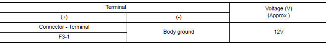
- Check voltage between A/C compressor harness connector F3 terminal 1 and ground
3.CHECK FUSE
Check 10A fuse (No. 41).
4.CHECK CIRCUIT CONTINUITY BETWEEN A/C RELAY IN IPDM E/R AND A/C COMPRESSOR
- Turn ignition switch OFF.
- Disconnect IPDM E/R connector F10 and A/C compressor connector F3.
- Check continuity between A/C compressor harness connector F3 (A) terminal 1 and IPDM E/R harness connector F10 (B) terminal 48.
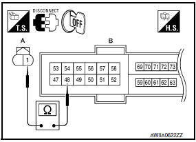
1 - 48: Continuity should exist.
5.CHECK A/C COMPRESSOR CIRCUIT FOR SHORT
Check continuity between A/C compressor harness connector F3 terminal 1 and ground.
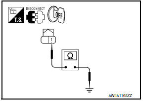
1 - Ground: Continuity should not exist.
6.CHECK WITH SELF-DIAGNOSIS FUNCTION OF CONSULT
- Using CONSULT, perform "SELF-DIAGNOSIS RESULTS" of HVAC.
- Check if any DTC No. is displayed in the self-diagnosis results.
NOTE: If DTC is displayed along with DTC U1000 or U1010, first diagnose the DTC U1000 or U1010.
7.CHECK A/C AUTO AMP. INPUT SIGNAL
Using CONSULT, check "On/Off" of "COMP REQ SIG" and "FAN REQ SIG" in "DATA MONITOR" of HVAC.
A/C SWITCH ON: COMP REQ SIG On
A/C SWITCH OFF: COMP REQ SIG Off
FAN CONTROL DIAL ON: FAN REQ SIG On
FAN CONTROL DIAL OFF: FAN REQ SIG Off
8.CHECK REFRIGERANT PRESSURE SENSOR
Check refrigerant pressure sensor.
 Blower motor
Description
COMPONENT DESCRIPTION
Brush-less Motor
The blower motor utilizes a brush-less motor with a rotating magnet.
Quietness is improved over previous motors where the brush was
the point ...
 Power supply and ground circuit
A/C AUTO AMP.
A/C AUTO AMP.: Description
COMPONENT DESCRIPTION
A/C Auto Amp. (Air Conditioner Automatic Amplifier)
The A/C auto amp. (1) has a built-in microcomputer that processes
information se ...
Other materials:
Washer switch
Description
Washer switch is integrated with combination switch (wiper and washer
switch).
Combination switch (wiper and washer switch) supplies ground and fuse #
38 from the IPEM E/R suppliespower for the front washer motor to
operate.
Component Inspection
1. CHECK WASHER SWITC ...
How to park with predicted course lines
WARNING
If the tires are replaced with different
sized tires, the predicted course lines
may be displayed incorrectly.
On a snow-covered or slippery road,
there may be a difference between the
predicted course line and the actual
course line.
If the battery is disconnected or becomes
discha ...
Wiring diagram
ELECTRONICALLY CONTROLLED POWER STEERING SYSTEM
Wiring Diagram
...
Nissan Maxima Owners Manual
- Illustrated table of contents
- Safety-Seats, seat belts and supplemental restraint system
- Instruments and controls
- Pre-driving checks and adjustments
- Monitor, climate, audio, phone and voice recognition systems
- Starting and driving
- In case of emergency
- Appearance and care
- Do-it-yourself
- Maintenance and schedules
- Technical and consumer information
Nissan Maxima Service and Repair Manual

0.0053