Nissan Maxima Service and Repair Manual: Main line between HVAC and A-bag circuit
Nissan Maxima Service and Repair Manual / Power outlet / Lan system / DTC/circuit diagnosis / Main line between HVAC and A-bag circuit
Diagnosis Procedure
1.CHECK HARNESS CONTINUITY (OPEN CIRCUIT)
- Turn the ignition switch OFF.
- Disconnect the battery cable from the negative terminal.
- Disconnect the following harness connectors.
- A/C auto amp.
- Harness connectors M1 and E30
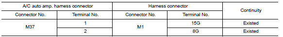
- Check the continuity between the A/C auto amp. harness connector and the harness connector.
 Main line between DLC and HVAC circuit
Diagnosis Procedure
1.CHECK HARNESS CONTINUITY (OPEN CIRCUIT)
Turn the ignition switch OFF.
Disconnect the battery cable from the negative terminal.
Disconnect the following harness connector ...
 Main line between A-bag and ABS circuit
Diagnosis Procedure
1.CHECK CONNECTOR
Turn the ignition switch OFF.
Disconnect the battery cable from the negative terminal.
Check the following terminals and connectors for damage, bend and ...
Other materials:
Wiring diagram
ELECTRONICALLY CONTROLLED POWER STEERING SYSTEM
Wiring Diagram
...
Blocking wheels
A. Blocks
B. Flat tire
Place suitable blocks at both the front and back
of the wheel diagonally opposite the flat tire to
prevent the vehicle from moving when it is jacked
up.
WARNING
Be sure to block the wheel as the vehicle
may move and result in personal injury.
Getting the spare tir ...
Specifications
Engine
This spark ignition system complies with the Canadian standard ICES-002.
Wheels and tires
Dimensions and weights
...
Nissan Maxima Owners Manual
- Illustrated table of contents
- Safety-Seats, seat belts and supplemental restraint system
- Instruments and controls
- Pre-driving checks and adjustments
- Monitor, climate, audio, phone and voice recognition systems
- Starting and driving
- In case of emergency
- Appearance and care
- Do-it-yourself
- Maintenance and schedules
- Technical and consumer information
Nissan Maxima Service and Repair Manual

© 2017-2026 Copyright www.nimainfo.com
0.007
0.007