Nissan Maxima Service and Repair Manual: Main line between DLC and HVAC circuit
Diagnosis Procedure
1.CHECK HARNESS CONTINUITY (OPEN CIRCUIT)
- Turn the ignition switch OFF.
- Disconnect the battery cable from the negative terminal.
- Disconnect the following harness connectors.
- ECM
- A/C auto amp.
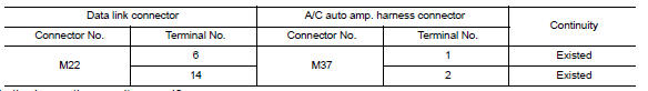
- Check the continuity between the data link connector and the A/C auto amp. harness connector.

 Main line between HVAC and A-bag circuit
Diagnosis Procedure
1.CHECK HARNESS CONTINUITY (OPEN CIRCUIT)
Turn the ignition switch OFF.
Disconnect the battery cable from the negative terminal.
Disconnect the following harness connector ...
Other materials:
Features of new model
BODY EXTERIOR PAINT COLOR
Body Exterior Paint Color
M= Metallic, S= Solid, 2S= Solid and Clear, 2P= 2-coat Pearl, 3P= 3-coat
pearl, PM= Pearl metallic. Black is solvent based, all others
are water based, - = Primerless diamond clear coat. ...
Remote engine start operating range
CAUTION
When the Intelligent Key battery is discharged
or other strong radio wave
sources are present near the operating
location, the Intelligent Key operating
range becomes narrower, and the Intelligent
Key may not function properly.
The remote engine start function can only be
used when t ...
ABS
System Diagram
System Description
Anti-Lock Braking System is a function that detects wheel revolution
while braking, electronically controls
braking force, and prevents wheel locking during sudden braking. It improves
handling stability and maneuverability
for avoiding obstacle ...
Nissan Maxima Owners Manual
- Illustrated table of contents
- Safety-Seats, seat belts and supplemental restraint system
- Instruments and controls
- Pre-driving checks and adjustments
- Monitor, climate, audio, phone and voice recognition systems
- Starting and driving
- In case of emergency
- Appearance and care
- Do-it-yourself
- Maintenance and schedules
- Technical and consumer information
Nissan Maxima Service and Repair Manual

0.0094