Nissan Maxima Owners Manual: System maintenance
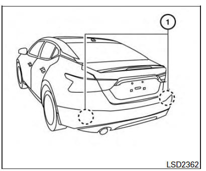
The two radar sensors 1 for the BSW and RCTA systems are located near the rear bumper.
Always keep the area near the radar sensors clean.
The radar sensors may be blocked by temporary ambient conditions such as splashing water, mist or fog.
The blocked condition may also be caused by objects such as ice, frost or dirt obstructing the radar sensors.
Check for and remove objects obstructing the area around the radar sensors.
Do not attach stickers (including transparent material), install accessories or apply additional paint near the radar sensors.
Do not strike or damage the area around the radar sensors. It is recommended that you visit a NISSAN dealer if the area around the radar sensors is damaged due to a collision.
Radio frequency statement
For USA
FCC : OAYSRR2B
This device complies with part 15 of the FCC Rules. Operation is subject to the following two conditions: (1) This device may not cause harmful interference, and (2) this device must accept any interference received, including interference that may cause undesired operation.
FCC Warning
Changes or modifications not expressly approved by the party responsible for compliance could void the user's authority to operate the equipment
For Canada
Applicable law: Canada 310
This device complies with Industry Canada licence-exempt RSS standard (s). Operation is subject to the following two conditions: (1) this device may not cause interference, and (2) this device must accept any interference, including interference that may cause undesired operation of the device.
Frequency bands: 24.05GHz - 24.25GHz
Output power: less than 20 milliwatts
 System temporarily unavailable
When radar blockage is detected, the system will
be deactivated automatically. The "Side Radar
Obstruction" warning message will appear and
the BSW/RCTA indicator (white) will blink A in
the v ...

Other materials:
Rear sunshade
Removal and Installation
Rear sunshade unit Front
REMOVAL
Remove the rear parcel shelf finisher. Refer to INT-24, "Removal
and Installation".
Remove the rear sunshade unit.
Remove the rear sunshade unit bolts.
Disconnect the rear sunshade unit harness
connector ...
TCM branch line circuit
Diagnosis Procedure
1.CHECK CONNECTOR
Turn the ignition switch OFF.
Disconnect the battery cable from the negative terminal.
Check the following terminals and connectors for damage, bend and
loose connection (unit side and connector
side).
TCM
Harness connector F1
Harness con ...
Ducts and grilles
Exploded View
Ducts
Side defroster nozzle (RH)
Front defroster nozzle
Side defroster nozzle (LH)
Upper ventilator duct
Heater and cooling unit assembly
Connector duct (LH)
Floor ventilator duct (LH)
Rear floor duct (LH)
Connector duct (center)
Rear ventilator duct (cen ...
Nissan Maxima Owners Manual
- Illustrated table of contents
- Safety-Seats, seat belts and supplemental restraint system
- Instruments and controls
- Pre-driving checks and adjustments
- Monitor, climate, audio, phone and voice recognition systems
- Starting and driving
- In case of emergency
- Appearance and care
- Do-it-yourself
- Maintenance and schedules
- Technical and consumer information
Nissan Maxima Service and Repair Manual

0.0062