Nissan Maxima Owners Manual: System temporarily unavailable
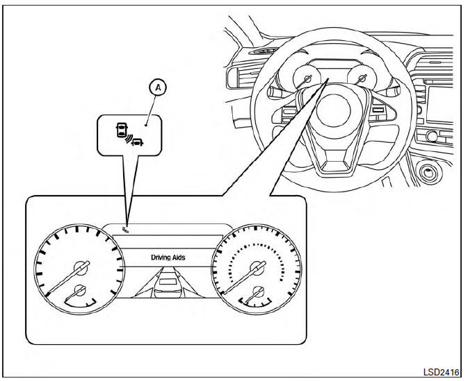
When radar blockage is detected, the system will be deactivated automatically. The "Side Radar Obstruction" warning message will appear and the BSW/RCTA indicator (white) will blink A in the vehicle information display.
The systems are not available until the conditions no longer exist.
The radar sensors may be blocked by temporary ambient conditions such as splashing water, mist or fog.
The blocked condition may also be caused by objects such as ice, frost or dirt obstructing the radar sensors.
NOTE:
If the BSW system stops working, the RCTA system will also stop working.
Action to take
When the above conditions no longer exist, the system will resume automatically.
Malfunction
When the RCTA system malfunctions, it will turn off automatically. The system malfunction warning message with the BSW/RCTA indicator (orange) will appear in the vehicle information display.
NOTE:
If the BSW system stops working, the RCTA system (if so equipped) will also stop working.
Action to take
Stop the vehicle in a safe location, place the vehicle in the P (Park) position, turn the engine off and restart the engine. If the message continues to appear, have the system checked. It is recommended that you visit a NISSAN dealer for this service.
 RCTA system limitations
WARNING
Listed below are the system limitations for
the RCTA system. Failure to operate the
vehicle in accordance with these system
limitations could result in serious injury or
death.
Alway ...
 System maintenance
The two radar sensors 1 for the BSW and
RCTA systems are located near the rear bumper.
Always keep the area near the radar sensors
clean.
The radar sensors may be blocked by temporary
amb ...
Other materials:
ECU diagnosis information
A/C AUTO AMP.
Reference Value
VALUES ON THE DIAGNOSIS TOOL
CONSULT MONITOR ITEM
A/C AUTO AMP. HARNESS CONNECTOR TERMINAL LAYOUT
TERMINALS AND REFERENCE VALUES FOR A/C AUTO AMP.
DTC Inspection Priority Chart
If some DTCs are displayed at the same time, perform inspections one b ...
Around View Monitor system operation
With the ignition switch in the ON position, move
the shift lever to the R (Reverse) position or press
the CAMERA button to operate the Around
View Monitor.
When the camera is first activated with the bird'seye
view in the display, a red icon (if so equipped)
will flash on the screen. This i ...
Mode door control system
System Diagram
System Description
The mode door is automatically controlled by the temperature setting, ambient
temperature, in-vehicle temperature,
intake temperature and amount of sunload.
SYSTEM OPERATION
The A/C auto amp. receives data from each of the sensors.
The A/C auto amp. ...
Nissan Maxima Owners Manual
- Illustrated table of contents
- Safety-Seats, seat belts and supplemental restraint system
- Instruments and controls
- Pre-driving checks and adjustments
- Monitor, climate, audio, phone and voice recognition systems
- Starting and driving
- In case of emergency
- Appearance and care
- Do-it-yourself
- Maintenance and schedules
- Technical and consumer information
Nissan Maxima Service and Repair Manual

0.0058