Nissan Maxima Service and Repair Manual: Power supply and ground circuit
AV CONTROL UNIT
AV CONTROL UNIT : Diagnosis Procedure
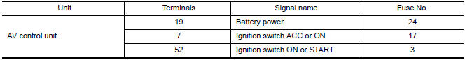
1.CHECK FUSES
Check that the following AV control unit fuses are not blown.
2.POWER SUPPLY CIRCUIT CHECK
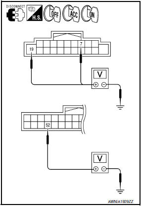
- Disconnect AV control unit connectors M160 and M163.
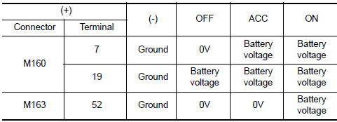
- Check voltage between the AV control unit connectors M160 and M163 and ground.
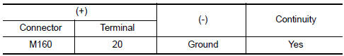
3.GROUND CIRCUIT CHECK
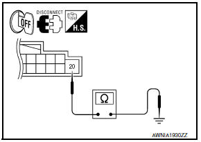
- Turn ignition switch OFF.
- Check continuity between AV control unit harness connector M160 and ground.
DISPLAY UNIT
DISPLAY UNIT : Diagnosis Procedure
1.CHECK FUSES
Check that the following display unit fuses are not blown.

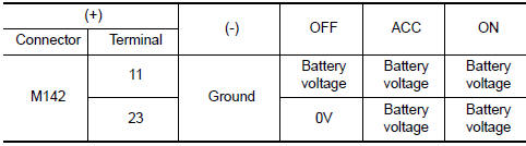
2.CHECK POWER SUPPLY CIRCUIT
- Turn ignition switch to ACC.
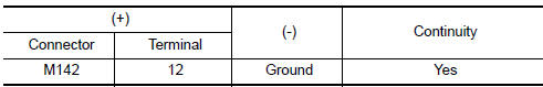
- Check voltage between display unit harness connector M142 and ground
3.CHECK GROUND CIRCUIT
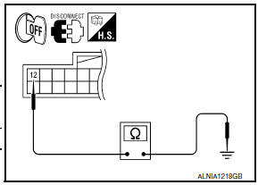
- Turn ignition switch OFF.
- Disconnect display unit connector.
- Check continuity between display unit harness connector M142 and ground.
A/C AND AV SWITCH ASSEMBLY
A/C AND AV SWITCH ASSEMBLY : Diagnosis Procedure
1.CHECK FUSE
Check that the A/C and AV switch assembly fuse is not blown

2.POWER SUPPLY CIRCUIT CHECK
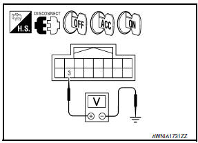
- Disconnect A/C and AV switch assembly connector M98.
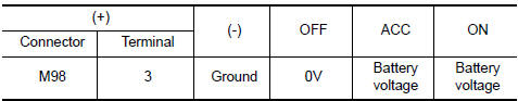
- Check voltage between the A/C and AV switch assembly connector M98 and ground.
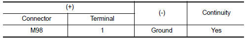
3.GROUND CIRCUIT CHECK
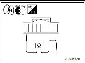
- Turn ignition switch OFF.
- Check continuity between A/C and AV switch assembly harness connector M98 and ground.
BOSE SPEAKER AMP
BOSE SPEAKER AMP : Diagnosis Procedure
1.CHECK FUSE
Check that the BOSE speaker amp. fuse is not blown.

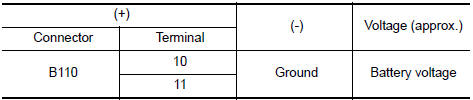
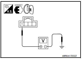
2.CHECK POWER SUPPLY CIRCUIT
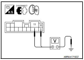
- Turn ignition switch OFF.
- Disconnect BOSE speaker amp. connector.
- Check voltage between BOSE speaker amp. harness connector B110 terminal 10, 11 and ground.
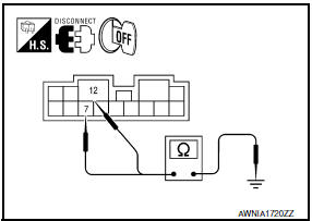
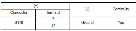
- Turn ignition switch OFF.
- Disconnect BOSE speaker amp. connector.
- Check continuity between BOSE speaker amp. harness connector B110 terminal 7,12 and ground.
REAR VIEW CAMERA
REAR VIEW CAMERA : Diagnosis Procedure
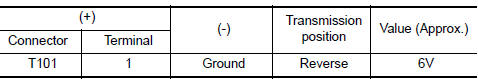
1.CHECK POWER SUPPLY CIRCUIT (REAR VIEW CAMERA SIDE)
- Turn ignition switch ON.
- Shift transmission into Reverse.
- Check voltage between rear view camera harness connector T101 and ground.
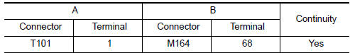
2.CHECK POWER SUPPLY CIRCUIT (CONTINUITY)
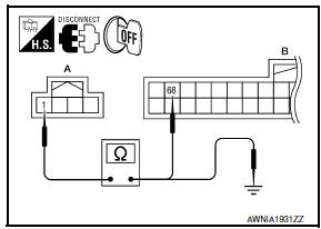
- Turn ignition switch OFF.
- Disconnect rear view camera and AV control unit connectors.
- Check continuity between rear view camera harness connector T101 (A) terminal 1 and AV control unit harness connector M164 (B) terminal 68.
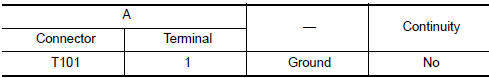
- Check continuity between rear view camera harness connector T101 (A) terminal 1 and ground
3.CHECK REVERSE POSITION INPUT SIGNAL
- Connect AV control unit connector.
- Turn ignition switch ON.
- Shift transmission into reverse.
- Check voltage between AV control unit harness connector M163 terminal 53 and ground.

4.CHECK GROUND CIRCUIT
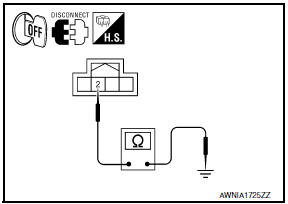
- Turn ignition switch OFF.
- Disconnect rear view camera harness connector.
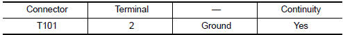
- Check continuity between rear view camera harness connector T101 terminal 2 and ground.
MICROPHONE
MICROPHONE : Diagnosis Procedure
1.CHECK POWER SUPPLY CIRCUIT
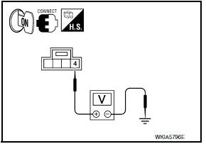
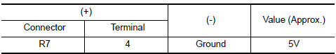
Check voltage between microphone harness connector R7 terminal 4 and ground.
2.CHECK POWER SUPPLY CIRCUIT (CONTINUITY)
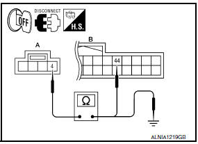
- Turn ignition switch OFF.
- Disconnect microphone and AV control unit harness connectors.
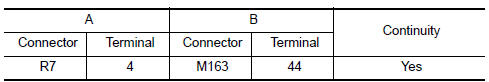
- Check continuity between microphone harness connector R7 (A) terminal 4 and AV control unit harness connector M163 (B) terminal 44.
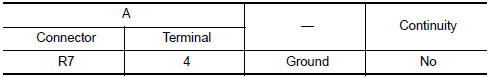
- Check continuity between microphone harness connector R7 (A) terminal 4 and ground.
3.CHECK GROUND CIRCUIT
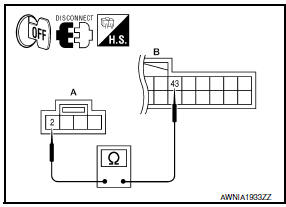
- Turn ignition switch OFF.
- Disconnect microphone harness connector R7 and AV control unit harness connector M163.
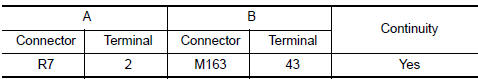
- Check continuity between microphone harness connector R7 (A) terminal 2 and AV control unit harness connector M163 (B) terminal 43.
 U1300 AV comm circuit
Description
U1300 is indicated when malfunction occurs in communication signal of multi
AV system. Indicated simultaneously,
without fail, with the malfunction of control units connected to AV co ...
 RGB digital image signal circuit
Description
Transmit the image displayed with AV control unit with RGB digital image
signal to the display unit.
Diagnosis Procedure
1.CHECK CONTINUITY RGB DIGITAL IMAGE SIGNAL CIRCUIT
Tu ...
Other materials:
ICC system operation
The ICC system maintains a selected distance
from the vehicle in front of you within the speed
range 0 to 90 mph (0 to 144km/h) up to the set
speed. The set speed can be selected by the
driver between 20 to 90 mph (32 to 144 km/h),
based on road conditions.
The vehicle travels at the set ...
Front fog lamp circuit
Description
The IPDM E/R (intelligent power distribution module engine room) controls the
front fog lamp relay based on inputs from the BCM over the CAN communication
lines. When the front fog lamp relay is energized, power flows from the front
fog lamp relay in the IPDM E/R to the front fog ...
Front seat belt
Exploded View
D-ring anchor
Adjustable upper anchor cover
Seat belt buckle
Seat belt buckle connector
Lower anchor bolt cover
Seat belt pre-tensioner connector
Seat belt retractor assembly
Adjustable upper anchor
D-ring anchor bolt
Seat belt buckle anchor bolt
Lower ...
Nissan Maxima Owners Manual
- Illustrated table of contents
- Safety-Seats, seat belts and supplemental restraint system
- Instruments and controls
- Pre-driving checks and adjustments
- Monitor, climate, audio, phone and voice recognition systems
- Starting and driving
- In case of emergency
- Appearance and care
- Do-it-yourself
- Maintenance and schedules
- Technical and consumer information
Nissan Maxima Service and Repair Manual

0.0056