Nissan Maxima Service and Repair Manual: RGB digital image signal circuit
Description
Transmit the image displayed with AV control unit with RGB digital image signal to the display unit.
Diagnosis Procedure
1.CHECK CONTINUITY RGB DIGITAL IMAGE SIGNAL CIRCUIT
- Turn ignition switch OFF.
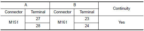
- Disconnect display unit connector M151 and AV control unit connector M161.
- Check continuity between display unit harness connector M151 (A) terminals 27, 28 and AV control unit harness connector M161 (B) terminals 23 and 24.
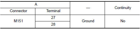
- Check continuity between display unit harness connector M151 (A) terminals 27, 28 and ground.
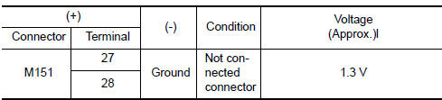
2.CHECK RGB DIGITAL IMAGE SIGNAL
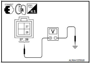
- Connect display unit connector M151 and AV control unit connector M161.
- Turn ignition switch ON.
- Check voltage between display unit harness connector M151 terminals 27, 28 and ground.
 Power supply and ground circuit
AV CONTROL UNIT
AV CONTROL UNIT : Diagnosis Procedure
1.CHECK FUSES
Check that the following AV control unit fuses are not blown.
2.POWER SUPPLY CIRCUIT CHECK
Disconnect AV control uni ...
 Composite image signal circuit
Description
AV control unit transmits the playback DVD image signal and AUX image signal
to the display unit.
Diagnosis Procedure
1.CHECK CONTINUITY COMPOSITE IMAGE SIGNAL CIRCUIT
Turn ig ...
Other materials:
Power seat for driver side
Wiring Diagram - Without Automatic Drive Positioner
...
P0031, P0032, P0051, P0052 A/F sensor 1 heater
Description
SYSTEM DESCRIPTION
The ECM performs ON/OFF duty control of the A/F sensor 1 heater corresponding
to the engine operating
condition to keep the temperature of A/F sensor 1 element within the specified
range.
DTC Logic
DTC DETECTION LOGIC
DTC CONFIRMATION PROCEDURE
1.PR ...
Avoiding collision and rollover
WARNING
Failure to operate this vehicle in a safe
and prudent manner may result in loss of
control or an accident.
Be alert and drive defensively at all times. Obey
all traffic regulations. Avoid excessive speed,
high speed cornering, or sudden steering maneuvers,
because these driving practi ...
Nissan Maxima Owners Manual
- Illustrated table of contents
- Safety-Seats, seat belts and supplemental restraint system
- Instruments and controls
- Pre-driving checks and adjustments
- Monitor, climate, audio, phone and voice recognition systems
- Starting and driving
- In case of emergency
- Appearance and care
- Do-it-yourself
- Maintenance and schedules
- Technical and consumer information
Nissan Maxima Service and Repair Manual

0.0071