Nissan Maxima Service and Repair Manual: Harness
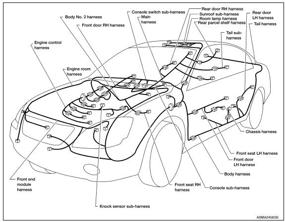
Harness Layout
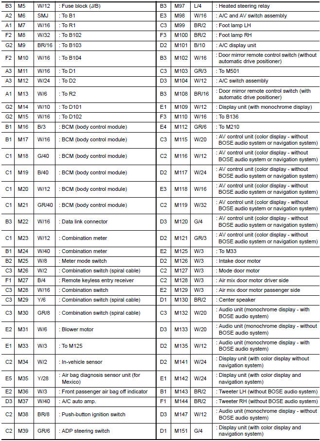
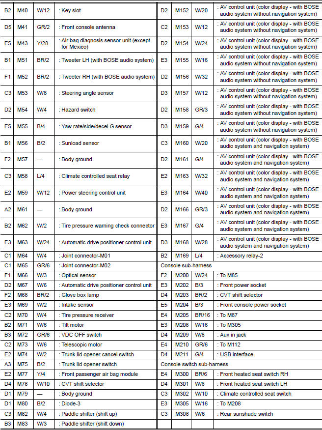
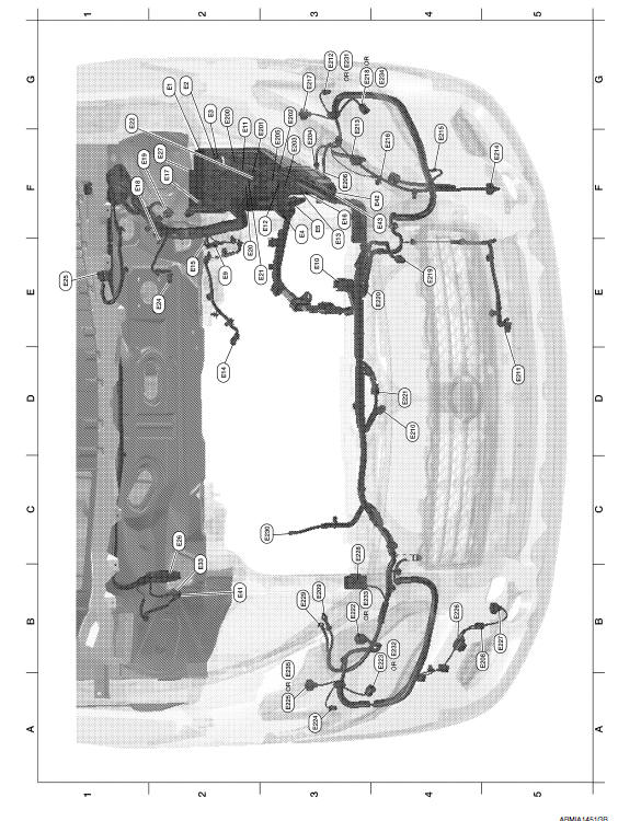
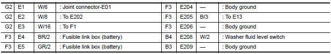
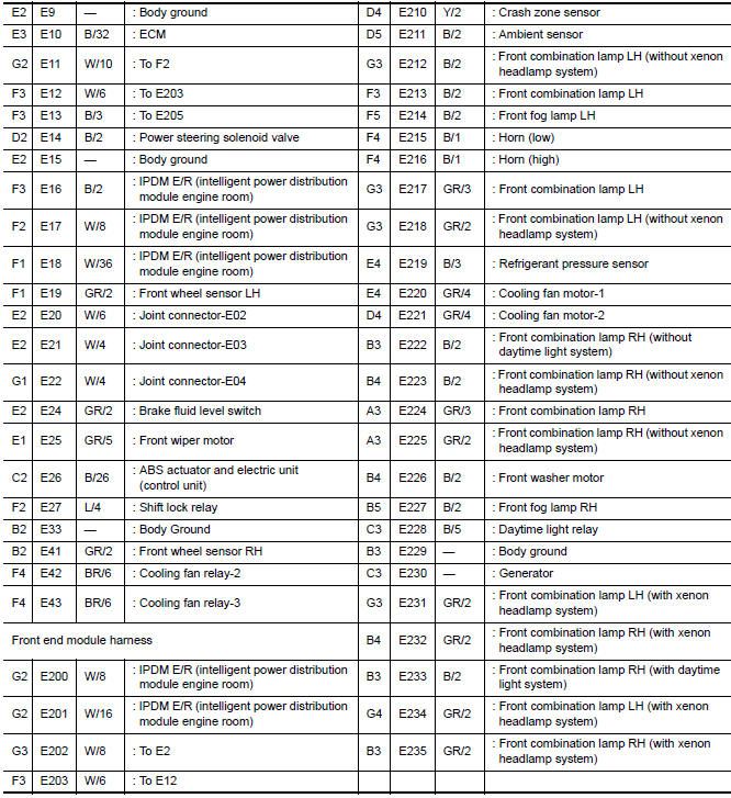
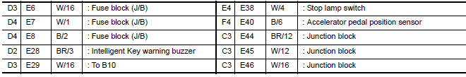
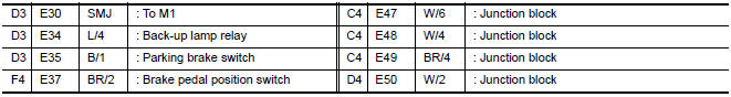
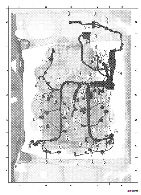
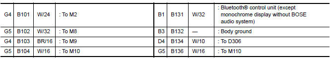
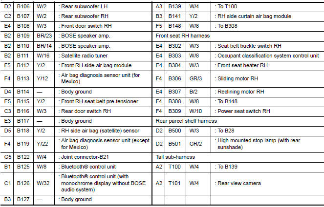
HOW TO READ HARNESS LAYOUT
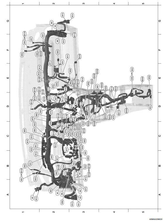
The following Harness Layouts use a map style grid to help locate connectors on the drawings:
- Main Harness, Console Sub-harness and Console Switch Subharness
- Engine Room Harness and Front End Module Harness
- Engine Room Harness (Passenger Compartment)
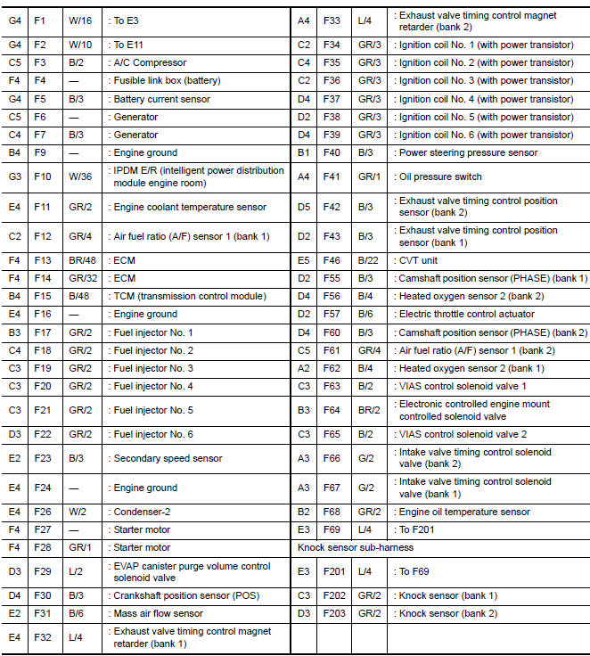
- Engine Control Harness and Knock Sensor Sub-harness
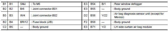
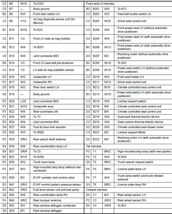
- Body Harness, Front Seat LH Harness, Tail Harness and Chassis Harness
- Body No. 2 Harness, Front Seat RH Harness, Rear Parcel Shelf Harness and Tail Sub-harness
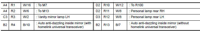
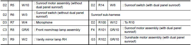
- Room Lamp Harness and Sunroof Sub-harness
To use the grid reference
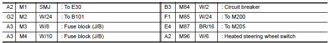
- Find the desired connector number on the connector list.
- Find the grid reference.
- On the drawing, find the crossing of the grid reference letter column and number row.
- Find the connector number in the crossing zone.
- Follow the line (if used) to the connector.
OUTLINE
MAIN HARNESS
ENGINE ROOM HARNESS
ENGINE ROOM HARNESS (PASSENGER COMPARTMENT)

ENGINE CONTROL HARNESS
BODY HARNESS
BODY NO. 2 HARNESS
ROOM LAMP HARNESS
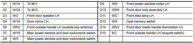
FRONT DOOR LH HARNESS
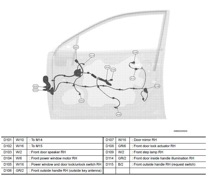
FRONT DOOR RH HARNESS
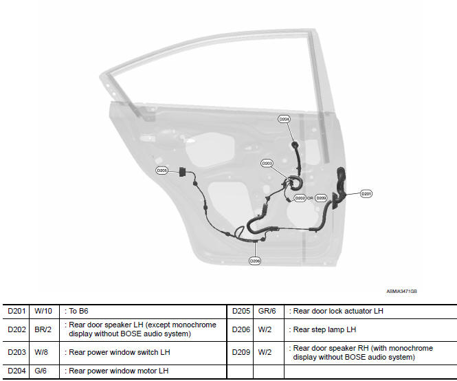
REAR DOOR LH HARNESS
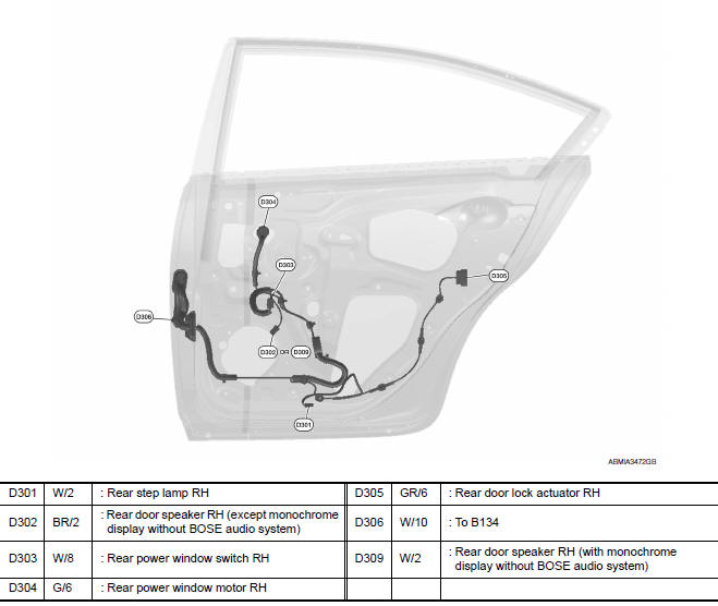
REAR DOOR RH HARNESS
 Ground
Ground Distribution
MAIN HARNESS
ENGINE ROOM HARNESS
FRONT END MODULE HARNESS
ENGINE CONTROL HARNESS
BODY HARNESS
BODY NO. 2 HARNESS
...
 Electrical units location
Electrical Units Location
ENGINE COMPARTMENT
PASSENGER COMPARTMENT
LUGGAGE COMPARTMENT
...
Other materials:
Headlamp (HI) circuit
Description
The IPDM E/R (intelligent power distribution module engine room) controls the
headlamp high relay based on inputs from the BCM over the CAN communication
lines. When the headlamp high relay is energized, power flows through fuses
48 and 49, located in the IPDM E/R. Power then flow ...
Rear view monitor system
System Diagram
System Description
When the shift selector is in the R position, the display unit shows a view
to the rear of the vehicle. Lines which
indicate the vehicle clearance and distances are also displayed.
Component Parts Location
Tweeter LH M51
Center speaker M130
...
NISSAN vehicle immobilizer system
The NISSAN Vehicle Immobilizer System will not
allow the engine to start without the use of a
registered key.
If the engine fails to start using a registered key
(for example, when interference is caused by
another registered key, an automated toll road
device or automatic payment device on ...
Nissan Maxima Owners Manual
- Illustrated table of contents
- Safety-Seats, seat belts and supplemental restraint system
- Instruments and controls
- Pre-driving checks and adjustments
- Monitor, climate, audio, phone and voice recognition systems
- Starting and driving
- In case of emergency
- Appearance and care
- Do-it-yourself
- Maintenance and schedules
- Technical and consumer information
Nissan Maxima Service and Repair Manual

0.007