Nissan Maxima Service and Repair Manual: U1300 AV comm circuit
Description
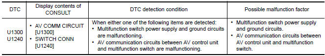
U1300 is indicated when malfunction occurs in communication signal of multi AV system. Indicated simultaneously, without fail, with the malfunction of control units connected to AV control unit with communication line.
Determine the possible malfunction cause from the table below.
SELF-DIAGNOSIS RESULTS DISPLAY ITEM
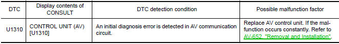
U1310 AV CONTROL UNIT
DTC Logic
 U1263 USB
DTC Logic
Diagnosis Procedure
1.CHECK USB HARNESS
Visually check USB harness. ...
 Power supply and ground circuit
AV CONTROL UNIT
AV CONTROL UNIT : Diagnosis Procedure
1.CHECK FUSES
Check that the following AV control unit fuses are not blown.
2.POWER SUPPLY CIRCUIT CHECK
Disconnect AV control uni ...
Other materials:
BCM (body control module)
Reference Value
NOTE: The Signal Tech II Tool (J-50190) can
be used to perform the following functions. Refer to the Signal Tech II User
Guide for additional information.
Activate and display TPMS transmitter IDs
Display tire pressure reported by the TPMS transmitter
Read TPMS DTCs
Re ...
Normal operating condition
Description
NOTE:
For Navigation system operation information, refer to Navigation system Owner's
Manual.
BASIC OPERATIONS
NOTE:
Locations stored in the Address Book and other memory functions may be lost if
the vehicle's battery is disconnected
or becomes discharged. If thi ...
Telescopic motor
Exploded View
Steering column assembly
Telescope motor
Telescope motor link bracket
Tilt motor
Tilt motor bolt cap
Removal and Installation
REMOVAL
Remove instrument lower panel LH. Refer to IP-19, "Removal and
Installation".
Remove lower knee protector (LH) bolts (A) a ...
Nissan Maxima Owners Manual
- Illustrated table of contents
- Safety-Seats, seat belts and supplemental restraint system
- Instruments and controls
- Pre-driving checks and adjustments
- Monitor, climate, audio, phone and voice recognition systems
- Starting and driving
- In case of emergency
- Appearance and care
- Do-it-yourself
- Maintenance and schedules
- Technical and consumer information
Nissan Maxima Service and Repair Manual

0.0057