Nissan Maxima Service and Repair Manual: Telescopic motor
Exploded View
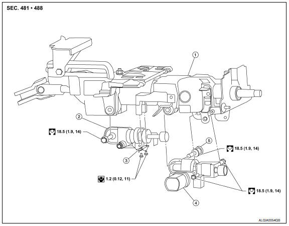
- Steering column assembly
- Telescope motor
- Telescope motor link bracket
- Tilt motor
- Tilt motor bolt cap
Removal and Installation
REMOVAL
- Remove instrument lower panel LH. Refer to IP-19, "Removal and Installation".
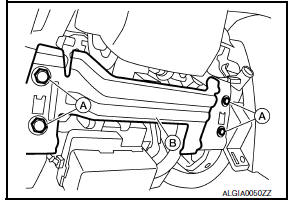
- Remove lower knee protector (LH) bolts (A) and the lower knee protector (LH) (B).
- Telescope the steering wheel to the full out position and tilt to highest position. NOTE: If either function is inoperative you can do this manually prior to installation.
- Remove the steering column covers. Refer to IP-11, "Removal and
Installation".
NOTE: The tilt/telescope switch can remain attached to the side cover.
- Remove telescope motor as follows.
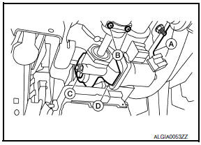
- Disconnect the harness connector (A) from the telescope motor.
- Remove the two telescope motor link screws (B) and telescope motor link bracket.
- Remove telescope motor bolt (C).
- Remove the telescope motor (D). NOTE: If the steering wheel could not be telescoped to full out position manually pull steering wheel to the full out position.
INSTALLATION
Installation is in the reverse order of removal.
NOTE:
- Adjust the telescope motor link to full out position and adjust as needed to fit into proper installed position.
- Inform customer that they will need to reset their Automatic Drive Positioner (ADP) settings.
 Tilt motor
Exploded View
Steering column assembly
Telescope motor
Telescope motor link bracket
Tilt motor
Tilt motor bolt cap
Removal and Installation
REMOVAL
Remove instrument lower pan ...
 Steering column
Without Electric Motor
-4. Steering column assembly nut tightening order
Steering wheel
Combination switch and spiral cable
Steering column assembly
Hole cover seal
Herbie c ...
Other materials:
Periodic maintenance
WHEEL HUB
On-vehicle Service
Check axle and suspension parts for excessive play, wear or damage.
Shake each rear wheel to check for excessive play.
Inspection
Rear Wheel Bearing
Check axial end play.
Axial end play : Refer to RAX-8, "Wheel Bearing (Rear)".
Check ...
U1001 can comm circuit
Description
CAN (Controller Area Network) is a serial communication line for real time
application. It is an on-vehicle multiplex
communication line with high data communication speed and excellent error
detection ability. Many electronic
control units are equipped onto a vehicle, and each ...
How to park with predicted course lines
WARNING
If the tires are replaced with different
sized tires, the predicted course lines
may be displayed incorrectly.
On a snow-covered or slippery road,
there may be a difference between the
predicted course line and the actual
course line.
If the battery is disconnected or becomes
discha ...
Nissan Maxima Owners Manual
- Illustrated table of contents
- Safety-Seats, seat belts and supplemental restraint system
- Instruments and controls
- Pre-driving checks and adjustments
- Monitor, climate, audio, phone and voice recognition systems
- Starting and driving
- In case of emergency
- Appearance and care
- Do-it-yourself
- Maintenance and schedules
- Technical and consumer information
Nissan Maxima Service and Repair Manual

0.0059