
Nissan Maxima Service and Repair Manual: Radiator core support
Exploded View
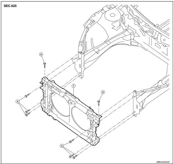
- Radiator core support
- Bolts
Removal and Installation
REMOVAL
- Remove front bumper. Refer to EXT-16, "Removal and Installation".
- Remove front combination lamps (LH/RH). Refer to EXL-154, "Removal and Installation" (Xenon Type), EXL-318, "Removal and Installation" (Halogen Type).
- Remove the radiator cooling fans. Refer to CO-16, "Removal and Installation".
- Remove the radiator. Refer to CO-14, "Removal and Installation".
- Remove the hood lock control. Refer to DLK-205, "HOOD LOCK CONTROL : Removal and Installation".
- Remove crash zone sensor. Refer to SR-27, "Removal and Installation".
- Disconnect power steering tube assembly from clips and position aside. Refer to ST-30, "Removal and Installation".
- Remove the horns. Refer to HRN-7, "Removal and Installation".
- Remove the harness clips from the radiator core support assembly and position the harness aside.
- Remove the bolts and the radiator core support.
INSTALLATION
Installation is in the reverse order of removal.
 Hood
Hood
HOOD ASSEMBLY
HOOD ASSEMBLY : Exploded View
Hood hinge cover (LH)
Hood stay (LH)
Hood hinge (LH)
Hood assembly
Hood bumper rubber
Seal
Hood insulator
Hood insulator clips
...
 Front fender
Exploded View
Front fender
Removal and Installation
REMOVAL
Remove the front combination lamp. Refer to EXL-154, "Removal and
Installation".
Remove the fender protector ...
Other materials:
P1722 vehicle speed
Description
The vehicle speed signal is transmitted from ABS actuator
and electric unit (control unit) to TCM via CAN communication
line.
DTC Logic
DTC DETECTION LOGIC
DTC CONFIRMATION PROCEDURE
CAUTION:
Always drive vehicle at a safe speed.
NOTE:
Immediately after performing any "DT ...
Air breather hose
Exploded View
Air cleaner case
Air breather hose
Transaxle assembly
Heater pipe
Clip
A. Paint mark
: Front
Removal and Installation
REMOVAL
Remove front air duct. Refer to EM-24, "Removal
and Installa ...
Removal and installation
SUNROOF UNIT ASSEMBLY
Inspection
WIND DEFLECTOR
Open glass lid assembly fully.
Visually check for proper installation, damaged/deteriorated
components, or foreign objects within mechanism.
Correct as required for
smooth operation.
Check for grease at the wind deflector arm (1) and ...
Nissan Maxima Owners Manual
- Illustrated table of contents
- Safety-Seats, seat belts and supplemental restraint system
- Instruments and controls
- Pre-driving checks and adjustments
- Monitor, climate, audio, phone and voice recognition systems
- Starting and driving
- In case of emergency
- Appearance and care
- Do-it-yourself
- Maintenance and schedules
- Technical and consumer information
Nissan Maxima Service and Repair Manual

0.0115