Nissan Maxima Service and Repair Manual: P1722 vehicle speed
Description
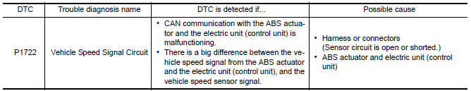
The vehicle speed signal is transmitted from ABS actuator and electric unit (control unit) to TCM via CAN communication line.
DTC Logic
DTC DETECTION LOGIC
DTC CONFIRMATION PROCEDURE
CAUTION: Always drive vehicle at a safe speed.
NOTE: Immediately after performing any "DTC CONFIRMATION PROCEDURE", always turn ignition switch OFF.
Then wait at least 10 seconds before performing the next test.
1.CHECK DTC DETECTION
 With CONSULT
-
Turn ignition switch ON.
-
Select "Data Monitor" in "TRANSMISSION".
-
Start engine and maintain the following conditions for at least 5 consecutive seconds.
ACC PEDAL OPEN : 1.0/8 or less
VEHICLE SPEED : 30 km/h (19 MPH) or more
Diagnosis Procedure
1.CHECK DTC WITH ABS ACTUATOR AND ELECTRIC UNIT (CONTROL UNIT)
 With CONSULT
Perform "Self Diagnostic Results" in "ABS".
2.CHECK DTC WITH TCM
 With CONSULT
Perform "Self Diagnostic Results" in "TRANSMISSION".
3.DETECT MALFUNCTIONING ITEMS
Check TCM connector pin terminals for damage or loose connection with harness connector.
 P1709 incompleted data writing
Description
When TCM does not store calibration data (individual
characteristic value) of each solenoid valve that is
stored in the ROM assembly (in the control valve), a malfunction is detected. ...
 P1723 speed sensor
Description
The secondary speed sensor detects the revolution of
parking gear and generates a pulse signal. The pulse
signal is sent to the TCM, which converts it into vehicle speed.
The prima ...
Other materials:
Shift lock system
Description
The selector lever cannot be shifted from "P" position to
any other position unless the ignition switch is in the
ON position and the brake pedal is depressed.
Component Function Check
1. CHECK CVT SHIFT LOCK OPERATION
Turn ignition switch ON.
Move selec ...
Power supply and ground circuit
Diagnosis Procedure
1. CHECK FUSES AND FUSIBLE LINK
Check that the following IPDM E/R fuses or fusible link are not blown.
2. CHECK POWER SUPPLY CIRCUIT
Turn ignition switch OFF.
Disconnect IPDM E/R connectors.
Check voltage between IPDM E/R harness connector and ground.
3. CHE ...
P2101 electric throttle control function
Description
Electric throttle control actuator consists of throttle control motor,
throttle position sensor, etc.
The throttle control motor is operated by the ECM and it opens and closes the
throttle valve.
The current opening angle of the throttle valve is detected by the throttle
pos ...
Nissan Maxima Owners Manual
- Illustrated table of contents
- Safety-Seats, seat belts and supplemental restraint system
- Instruments and controls
- Pre-driving checks and adjustments
- Monitor, climate, audio, phone and voice recognition systems
- Starting and driving
- In case of emergency
- Appearance and care
- Do-it-yourself
- Maintenance and schedules
- Technical and consumer information
Nissan Maxima Service and Repair Manual

0.006