Nissan Maxima Service and Repair Manual: P1709 incompleted data writing
Description
When TCM does not store calibration data (individual characteristic value) of each solenoid valve that is stored in the ROM assembly (in the control valve), a malfunction is detected.
DTC Logic
DTC DETECTION LOGIC
DTC CONFIRMATION PROCEDURE
NOTE: Immediately after performing any "DTC CONFIRMATION PROCEDURE", always turn ignition switch OFF.
Then wait at least 10 seconds before performing the next test.
1.CHECK DTC DETECTION
 With CONSULT
-
Turn ignition switch OFF.
-
Wait for at least 10 consecutive seconds.
-
Turn ignition switch ON.
-
Perform "Self Diagnostic Results" in "TRANSMISSION".
Diagnosis Procedure
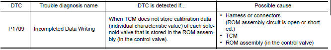
1.CHECK HARNESS BETWEEN TCM AND CVT UNIT HARNESS CONNECTOR (ROM ASSEMBLY) (PART 1)
-
Turn ignition switch OFF.
-
Disconnect TCM connector and CVT unit connector.
-
Check continuity between TCM vehicle side harness connector terminals and CVT unit vehicle side harness connector terminal.
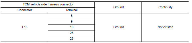
2.CHECK HARNESS BETWEEN TCM AND CVT UNIT HARNESS CONNECTOR (ROM ASSEMBLY) (PART 2)
Check continuity between TCM vehicle side harness connector terminals and ground.
3.CHECK TCM POWER SUPPLY AND GROUND CIRCUIT
Check TCM power supply and ground circuit. Refer to TM-95, "Diagnosis Procedure".
4.REPLACE TCM
-
Replace the TCM. Refer to TM-168, "Exploded View".
-
Perform "DTC CONFIRMATION PROCEDURE". Refer to TM-99, "DTC Logic".
 P1705 TP sensor
Description
The electric throttle control actuator consists of
throttle control motor, accelerator pedal position sensor, throttle
position sensor, etc. The actuator sends a signal to the ECM, an ...
 P1722 vehicle speed
Description
The vehicle speed signal is transmitted from ABS actuator
and electric unit (control unit) to TCM via CAN communication
line.
DTC Logic
DTC DETECTION LOGIC
DTC CONFIRMATION PROCE ...
Other materials:
B1113 - B1115 satellite sensor RH
Description
DTC B1113 - B1115 SATELLITE SENSOR RH
The satellite sensor RH is wired to the air bag diagnosis sensor unit. The
air bag diagnosis sensor unit willmonitor the satellite sensor RH for
internal failures and its circuits for communication errors.
PART LOCATION
DTC Logic
DTC DETECTI ...
Front fog lamp system
Wiring Diagram
...
Precaution
PRECAUTIONS
Precaution for Supplemental Restraint System (SRS) "AIR BAG" and "SEAT
BELT
PRE-TENSIONER"
The Supplemental Restraint System such as "AIR BAG" and "SEAT BELT PRE-TENSIONER",
used along
with a front seat belt, helps to reduce the risk or severity of injury to ...
Nissan Maxima Owners Manual
- Illustrated table of contents
- Safety-Seats, seat belts and supplemental restraint system
- Instruments and controls
- Pre-driving checks and adjustments
- Monitor, climate, audio, phone and voice recognition systems
- Starting and driving
- In case of emergency
- Appearance and care
- Do-it-yourself
- Maintenance and schedules
- Technical and consumer information
Nissan Maxima Service and Repair Manual

0.0075