Nissan Maxima Service and Repair Manual: B260A ignition relay
Description
BCM turns ON the following relays to ignition power supply to each ECU when the ignition switch is turned ON.
- Ignition relay-1 (inside IPDM E/R)
- Ignition relay-2 (inside fuse block (J/B))
- Front blower motor relay
BCM checks any ignition relay ON request for consistency with the actual ignition relay operation status.
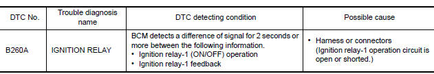
DTC Logic
DTC DETECTION LOGIC
NOTE:
- If DTC B260A is displayed with DTC U1000, first perform the trouble diagnosis for DTC U1000. Refer to PCS-44, "DTC Logic".
- If DTC B260A is displayed with DTC U1010, first perform the trouble diagnosis for DTC U1010. Refer to PCS-45, "DTC Logic".
- If DTC B260A is displayed with DTC B261A, first perform the trouble diagnosis for DTC B261A. Refer to PCS-60, "DTC Logic".
DTC CONFIRMATION PROCEDURE
1. PERFORM DTC CONFIRMATION PROCEDURE
- Turn ignition switch ON under the following conditions, and wait for at least 2 seconds.
- CVT selector lever is in the P or N position.
- Release the brake pedal.
- Check "Self diagnostic result" with CONSULT.
Diagnosis Procedure
1.CHECK DATA MONITOR
- Turn ignition switch ON.
- Check IGN RLY1-REQ and IGN RLY status with CONSULT
2.CHECK CAN COMMUNICATION
Check CAN communication.
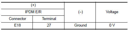
3.CHECK IGNITION RELAY-1 SIGNAL
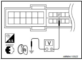
- Turn ignition switch OFF.
- Check voltage between IPDM E/R harness connector and ground.
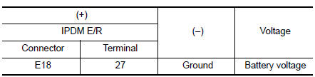
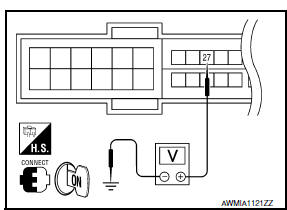
- Turn ignition switch ON.
- Check voltage between IPDM E/R harness connector and ground.
 B2553 ignition relay
Description
BCM turns ON the following relays to ignition power supply to each ECU when
the ignition switch is turned
ON.
Ignition relay-1 (inside IPDM E/R)
Ignition relay-2 (inside fuse bl ...
 B2614 ACC relay circuit
Description
BCM controls the various electrical components and simultaneously supplies
power according to the power
supply position.
BCM checks the power supply position internally.
DTC Logic ...
Other materials:
ECU diagnosis information
A/C AUTO AMP.
Reference Value
VALUES ON THE DIAGNOSIS TOOL
CONSULT MONITOR ITEM
A/C AUTO AMP. HARNESS CONNECTOR TERMINAL LAYOUT
TERMINALS AND REFERENCE VALUES FOR A/C AUTO AMP.
DTC Inspection Priority Chart
If some DTCs are displayed at the same time, perform inspections one b ...
Rear combination lamp
Disassembly and Assembly
Rear combination lamp
Rear side marker lamp socket
Rear side marker lamp bulb
Rear turn signal lamp socket
Rear turn signal lamp bulb
Back-up lamp socket
Back-up lamp bulb
DISASSEMBLY
Rotate the rear side marker lamp socket counterclockwise and ...
Preparation
Special Service Tool
The actual shapes of the tools may differ from those illustrated here.
Commercial Service Tool
...
Nissan Maxima Owners Manual
- Illustrated table of contents
- Safety-Seats, seat belts and supplemental restraint system
- Instruments and controls
- Pre-driving checks and adjustments
- Monitor, climate, audio, phone and voice recognition systems
- Starting and driving
- In case of emergency
- Appearance and care
- Do-it-yourself
- Maintenance and schedules
- Technical and consumer information
Nissan Maxima Service and Repair Manual

0.0069