Nissan Maxima Service and Repair Manual: B2553 ignition relay
Description
BCM turns ON the following relays to ignition power supply to each ECU when the ignition switch is turned ON.
- Ignition relay-1 (inside IPDM E/R)
- Ignition relay-2 (inside fuse block (J/B))
- Front blower motor relay
BCM checks any ignition relay ON request for consistency with the actual ignition relay operation status.
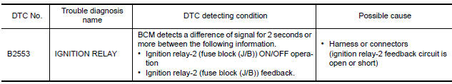
DTC Logic
DTC DETECTION LOGIC
DTC CONFIRMATION PROCEDURE
1. PERFORM DTC CONFIRMATION PROCEDURE
- Turn ignition switch ON under the following conditions, and wait for at least 2 seconds.
- CVT selector lever is in the P or N position.
- Release brake pedal.
- Check "Self diagnostic result" with CONSULT.
Diagnosis Procedure
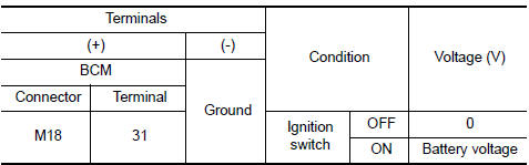
1. CHECK IGNITION RELAY-2 FEEDBACK INPUT SIGNAL
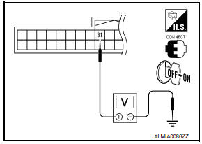
Check voltage between BCM harness connector and ground under the following conditions.
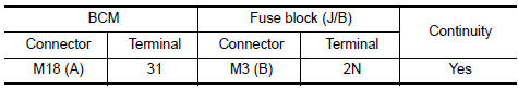
2. CHECK IGNITION RELAY-2 FEEDBACK CIRCUIT
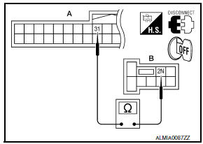
- Turn ignition switch OFF.
- Disconnect BCM and fuse block (J/B).
- Check continuity between BCM harness connector (A) and fuse block (J/B) harness connector (B).
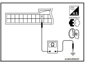
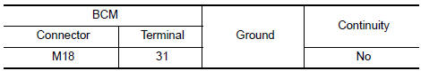
- Check continuity between BCM harness connector and ground.
3. CHECK INTERMITTENT INCIDENT
 U1010 control unit (CAN)
DTC Logic
DTC DETECTION LOGIC
Diagnosis Procedure
1. REPLACE BCM
When DTC U1010 is detected, replace BCM. ...
 B260A ignition relay
Description
BCM turns ON the following relays to ignition power supply to each ECU when
the ignition switch is turned
ON.
Ignition relay-1 (inside IPDM E/R)
Ignition relay-2 (inside fuse bl ...
Other materials:
Tilt sensor
Description
The tilt sensor is installed to the steering column assembly.
The pulse signal is input to the driver seat control unit when the tilt
is operated.
The driver seat control unit counts the pulse and calculates the
tilt amount of the steering column.
Component Function Chec ...
B26e1 no reception of engine status signal
Description
BCM receives the engine status signal from ECM via CAN
communication.
DTC Logic
DTC DETECTION LOGIC
NOTE:
If DTC B26E1 is displayed with DTC
U1000, first perform the trouble diagnosis for DTC U1000. Refer to
SEC-29, "DTC Logic".
If DTC B26E1 is displayed with D ...
Main line between HVAC and A-bag circuit
Diagnosis Procedure
1.CHECK HARNESS CONTINUITY (OPEN CIRCUIT)
Turn the ignition switch OFF.
Disconnect the battery cable from the negative terminal.
Disconnect the following harness connectors.
A/C auto amp.
Harness connectors M1 and E30
Check the continuity between the A/C au ...
Nissan Maxima Owners Manual
- Illustrated table of contents
- Safety-Seats, seat belts and supplemental restraint system
- Instruments and controls
- Pre-driving checks and adjustments
- Monitor, climate, audio, phone and voice recognition systems
- Starting and driving
- In case of emergency
- Appearance and care
- Do-it-yourself
- Maintenance and schedules
- Technical and consumer information
Nissan Maxima Service and Repair Manual

0.0058