Nissan Maxima Service and Repair Manual: U1010 control unit (CAN)
DTC Logic
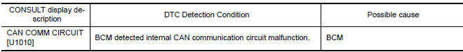
DTC DETECTION LOGIC
Diagnosis Procedure
1. REPLACE BCM
When DTC U1010 is detected, replace BCM.
 U1000 CAN comm circuit
Description
DTC Logic
DTC DETECTION LOGIC
NOTE:
U1000 can be set if a module harness was disconnected and reconnected, perhaps
during a repair. Confirm
that there are actual CAN diagnostic sy ...
 B2553 ignition relay
Description
BCM turns ON the following relays to ignition power supply to each ECU when
the ignition switch is turned
ON.
Ignition relay-1 (inside IPDM E/R)
Ignition relay-2 (inside fuse bl ...
Other materials:
Air conditioner system refrigerant and oil recommendations
The air conditioner system in your NISSAN
vehicle must be charged with the refrigerant
HFC-134a (R-134a) and Genuine
NISSAN A/C System Oil Type ND-OIL8 or
the exact equivalents.
CAUTION
The use of any other refrigerant or oil may
cause severe damage to the air conditioning
system and may req ...
The ambient temperature display is incorrect
Description
The displayed ambient air temperature is higher
than the actual temperature.
The displayed ambient air temperature is lower
than the actual temperature.
Diagnosis Procedure
1.COMBINATION METER INPUT SIGNAL
Select "METER/M&A" on CON ...
Power seat switch ground circuit
Diagnosis Procedure
1. CHECK POWER SEAT SWITCH LH GROUND CIRCUIT
Turn ignition switch OFF.
Disconnect power seat switch LH.
Check continuity between power seat switch LH connector and
ground.
...
Nissan Maxima Owners Manual
- Illustrated table of contents
- Safety-Seats, seat belts and supplemental restraint system
- Instruments and controls
- Pre-driving checks and adjustments
- Monitor, climate, audio, phone and voice recognition systems
- Starting and driving
- In case of emergency
- Appearance and care
- Do-it-yourself
- Maintenance and schedules
- Technical and consumer information
Nissan Maxima Service and Repair Manual

0.0072