Nissan Maxima Service and Repair Manual: Mode door control system
System Diagram
System Description
The mode door is automatically controlled by the temperature setting, ambient temperature, in-vehicle temperature, intake temperature and amount of sunload.
SYSTEM OPERATION
- The A/C auto amp. receives data from each of the sensors.
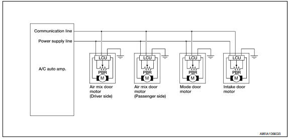
- The A/C auto amp. sends the air mix door, the mode door and the intake door opening angle data to the air mix door motor LCU(s), the mode door motor LCU and the intake door motor LCU.
- The air mix door motor(s), the mode door motor and the intake door motor read their respective signals according to the address signal. Opening angle indication signals received from the A/C auto amp. and each of the motor position sensors, are compared by the LCUs in each door motor with the existing decision and opening angles.
- Next, HOT/COLD, DEF/VENT or FRE/REC operation is selected. The newly selected data is returned to the A/C auto amp.
Door Motor Circuit
Mode Door Control Specification
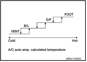
Mode position can be selected manually by pressing the MODE switch or the DEF switch on the A/C switch assembly. Pressing the AUTO switch allows automatic control by the A/C auto amp. During the automatic control of a mode position, a mode door position (VENT, B/L, FOOT, or D/F) is selected based on a target air mix door opening angle and the sunload sensor, calculated by the A/C auto amp. In addition, the D/F is selected to prevent windshield fogging only when ambient temperature is extremely low.
 Automatic air conditioner system
System Diagram
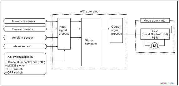
CONTROL SYSTEM
The control system consists of input sensors, switches, the A/C auto amp.
(microcomputer) and outputs. The
relationship of these components is as shown in the figure ...
 Air mix door control system
System Diagram
System Description
The air mix doors are automatically controlled so that in-vehicle temperature
is maintained at a predetermined
value by the temperature setting, ambient tem ...
Other materials:
System maintenance
CAUTION
Do not use alcohol, benzine or thinner
to clean the camera. This will cause
discoloration.
Do not damage the camera as the monitor
screen may be adversely affected.
If dirt, rain or snow accumulates on the camera
1 , the RearView Monitor may not display objects
clearly. ...
Symptom diagnosis
REFRIGERATION SYSTEM SYMPTOMS
WITH COLOR DISPLAY
WITH COLOR DISPLAY : Trouble Diagnoses for Abnormal Pressure
Whenever system′s high and/or low side pressure is abnormal, diagnose using a
manifold gauge. The marker above the gauge scale in the following tables
indicates the standard (us ...
Harness
Harness Layout
HOW TO READ HARNESS LAYOUT
The following Harness Layouts use a map style grid to help locate
connectors on the drawings:
Main Harness, Console Sub-harness and Console Switch Subharness
Engine Room Harness and Front End Module Harness
Engine Room Harness (Passenger Comp ...
Nissan Maxima Owners Manual
- Illustrated table of contents
- Safety-Seats, seat belts and supplemental restraint system
- Instruments and controls
- Pre-driving checks and adjustments
- Monitor, climate, audio, phone and voice recognition systems
- Starting and driving
- In case of emergency
- Appearance and care
- Do-it-yourself
- Maintenance and schedules
- Technical and consumer information
Nissan Maxima Service and Repair Manual

0.0076