Nissan Maxima Service and Repair Manual: U1000 CAN comm circuit
Description
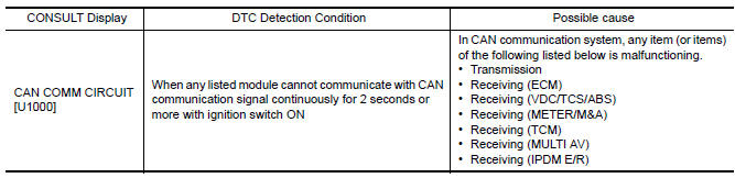
DTC Logic
DTC DETECTION LOGIC
NOTE: U1000 can be set if a module harness was disconnected and reconnected, perhaps during a repair. Confirm that there are actual CAN diagnostic symptoms and a present DTC by performing the Self Diagnostic Result procedure.
Diagnosis Procedure
1. PERFORM SELF DIAGNOSTIC
- Turn ignition switch ON and wait for 2 seconds or more.
- Check "SELF- DIAG RESULTS".

 U1010 control unit (CAN)
DTC Logic
DTC DETECTION LOGIC
Diagnosis Procedure
1. REPLACE BCM
When DTC U1010 is detected, replace BCM. ...
Other materials:
Front door speaker
Removal and Installation
REMOVAL
Remove the front door finisher. Refer to INT-18, "Removal and
Installation".
Remove the front door speaker screws (A).
Disconnect the harness connector from the front door speaker
(1) and remove.
Remove the front door speaker spacer screws (B) and ...
Main line between HVAC and A-bag circuit
Diagnosis Procedure
1.CHECK HARNESS CONTINUITY (OPEN CIRCUIT)
Turn the ignition switch OFF.
Disconnect the battery cable from the negative terminal.
Disconnect the following harness connectors.
A/C auto amp.
Harness connectors M1 and E30
Check the continuity between the A/C au ...
P0550 PSP sensor
Description
Power steering pressure (PSP) sensor is installed to the power steering
high-pressure tube and detects a
power steering load.
This sensor is a potentiometer which transforms the power steering load into
output voltage, and emits the
voltage signal to the ECM. The ECM controls ...
Nissan Maxima Owners Manual
- Illustrated table of contents
- Safety-Seats, seat belts and supplemental restraint system
- Instruments and controls
- Pre-driving checks and adjustments
- Monitor, climate, audio, phone and voice recognition systems
- Starting and driving
- In case of emergency
- Appearance and care
- Do-it-yourself
- Maintenance and schedules
- Technical and consumer information
Nissan Maxima Service and Repair Manual

0.0062