Nissan Maxima Service and Repair Manual: U1000 CAN comm circuit
Description
CAN (Controller Area Network) is a serial communication line for real time application. It is an on-vehicle multiplex communication line with high data communication speed and excellent error detection ability. Many electronic control units are equipped onto a vehicle, and each control unit shares information and links with other control units during operation (not independent). In CAN communication, control units are connected with two communication lines (CAN-H line, CAN-L line) allowing a high rate of information transmission with less wiring.
Each control unit transmits/receives data but selectively reads required data only.
CAN Communication Signal Chart. Refer to LAN-14, "How to Use CAN Communication Signal Chart".
DTC Logic
DTC DETECTION LOGIC
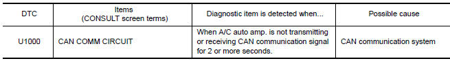
Diagnosis Procedure
1.CHECK WITH SELF-DIAGNOSIS FUNCTION OF CONSULT
- Turn ignition switch ON and wait for 2 or more seconds.
- Using CONSULT, perform "SELF-DIAGNOSIS RESULTS" of HVAC

 U1010 control unit (CAN)
Description
Initial diagnosis of A/C auto amp.
DTC Logic
DTC DETECTION LOGIC
Diagnosis Procedure
1.CHECK WITH SELF-DIAGNOSIS FUNCTION OF CONSULT
Using CONSULT, perform "SELF-DIAGNOSIS RESULT ...
Other materials:
P0441 evap control system
DTC Logic
DTC DETECTION LOGIC
NOTE:
If DTC P0441 is displayed with other DTC such as P2122, P2123, P2127, P2128 or
P2138, first perform
trouble diagnosis for other DTC.
In this evaporative emission (EVAP) control system, purge flow occurs during
non-closed throttle conditions.
Purge vo ...
Intake Manifold Collector
Removal and Installation
Intake manifold collector
Intake manifold collector gasket
Electric throttle control actuator gasket
Electric throttle control actuator
Refer to INSTALLATION
Refer to INSTALLATION
WARNING: To avoid the danger of being
scalded, do not drain the coolan ...
Main power window and door lock/unlock switch
Removal and Installation
REMOVAL
Remove the front door grip cover. Refer to DLK-214, "FRONT DOOR :
Removal and Installation".
Remove the clip (A) from the door grip using a suitable tool.
Release the metal clip and lift the main power window and door
lock/unlock swit ...
Nissan Maxima Owners Manual
- Illustrated table of contents
- Safety-Seats, seat belts and supplemental restraint system
- Instruments and controls
- Pre-driving checks and adjustments
- Monitor, climate, audio, phone and voice recognition systems
- Starting and driving
- In case of emergency
- Appearance and care
- Do-it-yourself
- Maintenance and schedules
- Technical and consumer information
Nissan Maxima Service and Repair Manual

0.0061