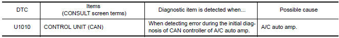
Nissan Maxima Service and Repair Manual: U1010 control unit (CAN)
Description
Initial diagnosis of A/C auto amp.
DTC Logic
DTC DETECTION LOGIC
Diagnosis Procedure
1.CHECK WITH SELF-DIAGNOSIS FUNCTION OF CONSULT
Using CONSULT, perform "SELF-DIAGNOSIS RESULTS" of HVAC.
 U1000 CAN comm circuit
Description
CAN (Controller Area Network) is a serial communication line for real time
application. It is an on-vehicle multiplex
communication line with high data communication speed and excellen ...
 B257B, B257C ambient sensor
Description
COMPONENT DESCRIPTION
Ambient Sensor
The ambient sensor (1) is installed to the front bumper
reinforcement.
It detects ambient temperature and converts it into a resistance
...
Other materials:
P0442 evap control system
DTC Logic
DTC DETECTION LOGIC
This diagnosis detects leakage in the EVAP purge line using engine intake
manifold vacuum.
If pressure does not increase, the ECM will check for leakage in the line
between the fuel tank and EVAP canister
purge volume control solenoid valve, under the followi ...
A-bag branch line circuit
Diagnosis Procedure
WARNING:
Always observe the following items for preventing accidental
activation.
- Before servicing, turn ignition switch OFF, disconnect battery negative
terminal, and wait 3 minutes
or more. (To discharge backup capacitor.)
- Never use unspecified tester or other ...
Charging system
System Diagram
System Description
The generator provides DC voltage to operate the vehicle's electrical system
and to keep the battery charged.
The voltage output is controlled by the IC regulator.
Component Description
...
Nissan Maxima Owners Manual
- Illustrated table of contents
- Safety-Seats, seat belts and supplemental restraint system
- Instruments and controls
- Pre-driving checks and adjustments
- Monitor, climate, audio, phone and voice recognition systems
- Starting and driving
- In case of emergency
- Appearance and care
- Do-it-yourself
- Maintenance and schedules
- Technical and consumer information
Nissan Maxima Service and Repair Manual

0.01