Nissan Maxima Service and Repair Manual: Basic inspection
DIAGNOSIS AND REPAIR WORKFLOW
Work Flow
OVERALL SEQUENCE
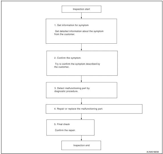
1.GET INFORMATION FOR SYMPTOM
Get detailed information from the customer about the symptom (the condition and the environment when the incident/malfunction occurred).
2.CONFIRM THE SYMPTOM
Try to confirm the symptom described by the customer. Verify relation between the symptom and the condition when the symptom is detected.
3.DETECT MALFUNCTIONING PART BY DIAGNOSTIC PROCEDURE
Inspect according to Diagnostic Procedure of the system.
4.REPAIR OR REPLACE THE MALFUNCTIONING PART
- Repair or replace the malfunctioning part.
- Reconnect parts or connectors disconnected during Diagnostic Procedure.
5.FINAL CHECK
Refer to confirmed symptom in step 2, and make sure that the symptom is not detected.
 Bluetooth control unit
Removal and Installation
REMOVAL
Disconnect the battery negative terminal. Refer to PG-67, "Removal
and Installation (Battery)".
Remove the trunk upper finisher. Refer to INT-23, "Exploded ...

Other materials:
Sunshade
Exploded View
Center bracket (RH)
Rear sunshade
Front sunshade
Center bracket (LH)
Sunshade carrier assembly Front
Removal and Installation
REMOVAL
Open glass lid and sunshades.
Remove the headlining. Refer to INT-33, "Removal and
Installation".
Release front sunsha ...
P0746 pressure control solenoid A
Description
The line pressure solenoid valve regulates the oil pump discharge pressure to
suit the driving condition in
response to a signal sent from the TCM.
DTC Logic
DTC DETECTION LOGIC
DTC CONFIRMATION PROCEDURE
CAUTION:
Always drive vehicle at a safe speed.
NOTE:
Immediately af ...
Child safety rear door lock
Child safety locks help prevent the rear doors
from being opened accidentally, especially when
small children are in the vehicle.
The child safety lock levers are located on the
edge of the rear doors.
When the lever is in the unlock position 2 , the
door can be opened from the outside ...
Nissan Maxima Owners Manual
- Illustrated table of contents
- Safety-Seats, seat belts and supplemental restraint system
- Instruments and controls
- Pre-driving checks and adjustments
- Monitor, climate, audio, phone and voice recognition systems
- Starting and driving
- In case of emergency
- Appearance and care
- Do-it-yourself
- Maintenance and schedules
- Technical and consumer information
Nissan Maxima Service and Repair Manual

0.0059