Nissan Maxima Service and Repair Manual: Power distribution system
System Description
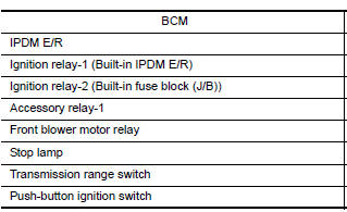
INPUT/OUTPUT SIGNAL CHART
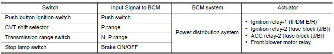
SYSTEM DESCRIPTION
- POWER DISTRIBUTION SYSTEM (PDS) is the system that BCM controls with the operation of the pushbutton ignition switch and performs the power distribution to each power circuit. This system is used instead of the mechanical power supply changing mechanism with the operation of the conventional key cylinder.
- The push-button ignition switch can be operated when Intelligent Key is in the following conditions. Refer to Engine Start Function for details.
- Intelligent Key is in the detection area of the interior antenna
- Insert Intelligent Key in to the key slot
- The push-button ignition switch operation is input to BCM as a signal. BCM changes the power supply position according to the status and operates the following relays to supply power to each power circuit.
- Ignition relay-1 (inside IPDM E/R)
- Ignition relay-2 (inside fuse block (J/B))
- ACC relay (inside fuse block (J/B))
- Front blower motor relay
NOTE: The engine switch operation changes due to the conditions of brake pedal, CVT selector lever and vehicle speed.
- The power supply position can be confirmed with the lighting of the indicators near the push-button ignition switch.
PUSH-BUTTON IGNITION SWITCH OPERATION PROCEDURE
The power supply position changing operation can be performed with the following operation.
NOTE:
- When an Intelligent Key is within the detection area of inside key antenna and when it is inserted in to the key slot, it is equivalent to the operations below.
- When starting the engine, the BCM monitors under the engine start conditions,
- Brake pedal operating condition
- CVT selector lever position
- Vehicle speed
- Unless each start condition is fulfilled, the engine will not respond regardless of how many times the engine switch is pressed. At that time, illumination repeats the position in the order of LOCK→ACC→ON→OFF
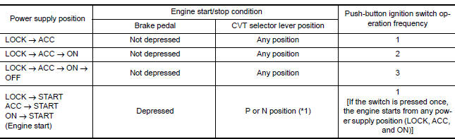
*1: When the CVT selector lever position is N position, the engine start condition is different according to the vehicle speed.
- At vehicle speed of 4 km/h (2 MPH) or less, the engine can start only when the brake pedal is depressed.
- At vehicle speed of 4 km/h (2 MPH) or more, the engine can start even if the brake pedal is not depressed. (It is the same as "Engine stall return operation while driving".)
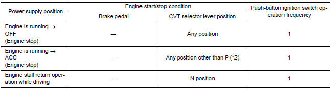
*2: When the CVT selector lever position is in any position other than P position and when the vehicle speed is 5 km/h or more, the engine stop condition is different.
- Press and hold the push-button ignition switch for 2 seconds or more. (When the push-button ignition switch is pressed for too short a time, the operation may be invalid, so properly press and hold to prevent the incorrect operation.)
- Press the push-button ignition switch 3 times or more within 1.5 seconds. (Emergency stop operation)
Component Parts Location
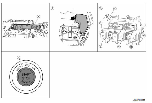
- BCM M16, M17, M18, M19, M21 (view with instrument panel removed)
- IPDM E/R E16, E17, E18 (contains IGN relay-1)
- A. Fuse block (J/B) M3, M4, M5, E6 B. IGN relay-2 C. ACC relay-1 D. Front blower motor relay
- Push-button ignition switch M38
Component Description

 Diagnosis system (BCM)
COMMON ITEM
COMMON ITEM : CONSULT Function (BCM - COMMON ITEM)
APPLICATION ITEM
CONSULT performs the following functions via CAN communication with BCM.
SYSTEM APPLICATION
BCM can perform the ...
Other materials:
Jump starting
To start your engine with a booster battery, the
instructions and precautions below must be followed.
WARNING
If done incorrectly, jump starting can
lead to a battery explosion, resulting in
severe injury or death. It could also
damage your vehicle.
Explosive hydrogen gas is always pre ...
Fog light switch
To turn the fog lights on, turn the headlight switch
to the position, then turn the fog
light
switch to the position.
To turn the fog lights on with the headlight switch
in the AUTO position, the headlights must be on,
then turn the fog light switch to the
position.
To turn the f ...
Audio system
System Diagram
System Description
AUDIO SYSTEM
The audio system consists of the following components
AV control unit
Display unit
BOSE speaker amp.
Window antenna
Steering wheel audio control switches
A/C and AV switch assembly
Front door speakers
Tweeters
Center speaker
...
Nissan Maxima Owners Manual
- Illustrated table of contents
- Safety-Seats, seat belts and supplemental restraint system
- Instruments and controls
- Pre-driving checks and adjustments
- Monitor, climate, audio, phone and voice recognition systems
- Starting and driving
- In case of emergency
- Appearance and care
- Do-it-yourself
- Maintenance and schedules
- Technical and consumer information
Nissan Maxima Service and Repair Manual

0.0062