
Nissan Maxima Owners Manual: System maintenance
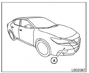
The sensor A is located behind the lower grille of the front bumper.
To keep the system operating properly, be sure to observe the following:
- Always keep the sensor area of the front bumper clean.
- Do not strike or damage the areas around the sensor.
- Do not cover or attach stickers or similar objects on the front bumper near the sensor area. This could cause failure or malfunction.
- Do not attach metallic objects near the sensor area (brush guard, etc.). This could cause failure or malfunction.
- Do not alter, remove or paint the front bumper.
Before customizing or restoring the front bumper, it is recommended that you visit a NISSAN dealer.
FCC Notice
For USA
This device complies with Part 15 of the FCC Rules. Operation is subject to the following two conditions:
1. This device may not cause harmful interference, and
2. This device must accept any interference received, including interference that may cause undesired operation.
FCC Warning
Changes or modification not expressly approved by the party responsible for compliance could void the user's authority to operate the equipment.
For Canada
This device complies with Industry Canada licence-exempt RSS standard(s). Operation is subject to the following two conditions: 1. This device may not cause interference, 2. This device must accept any interference, including interference that may cause undesired operation of the device.
 System malfunction
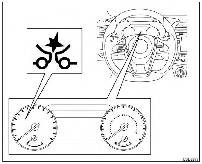
If the PFCW system malfunctions, it will be
turned off automatically, a chime will sound, the
FEB system warning light (orange) will illuminate
and the warning message [Malfunction] will appear
in ...
 Driver Attention Alert (if so equipped)
WARNING
Failure to follow the warnings and instructions
for proper use of the Driver Attention
Alert system could result in serious injury
or death.
The Driver Attention Alert system is only
a w ...
Other materials:
B2618 BCM
Description
BCM controls the various electrical components and simultaneously supplies
power according to the power
supply position.
BCM checks the power supply position internally.
DTC Logic
DTC DETECTION LOGIC
NOTE:
If DTC B2618 is displayed with DTC U1000, first perform the
trou ...
Diagnosis system (HVAC)
CONSULT Function
CONSULT can display each diagnosis item using the diagnosis test modes as
shown.
CONSULT application items
SELF DIAGNOSTIC RESULT
Display Item List
*: Perform self-diagnosis under sunshine. When performing indoors, aim a
light (more than 60 W) at sunload sensor, ...
Hands-free phone system
System Diagram
System Description
Refer to the Owner's Manual for Bluetooth telephone system operating
instructions.
NOTE: Cellular telephones must have their wireless
connection set up (paired) before using the Bluetooth telephone system.
Bluetooth telephone system allows users who have ...
Nissan Maxima Owners Manual
- Illustrated table of contents
- Safety-Seats, seat belts and supplemental restraint system
- Instruments and controls
- Pre-driving checks and adjustments
- Monitor, climate, audio, phone and voice recognition systems
- Starting and driving
- In case of emergency
- Appearance and care
- Do-it-yourself
- Maintenance and schedules
- Technical and consumer information
Nissan Maxima Service and Repair Manual

0.0082