Nissan Maxima Service and Repair Manual: U1243 display unit
Description
| Part name | Description |
| DISPLAY UNIT |
|
DTC Logic
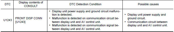
Diagnosis Procedure
1.CHECK DISPLAY UNIT POWER SUPPLY AND GROUND CIRCUIT
Check display unit power supply and ground circuit
2.CHECK CONTINUITY OF COMMUNICATION CIRCUIT
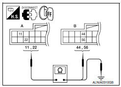
- Turn ignition switch OFF.
- Disconnect display unit connector and AV control unit connector.
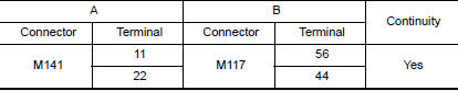
- Check continuity between display unit harness connector M141 (A) terminals 11, 22 and AV control unit harness connector M117 (B) terminals 56, 44.
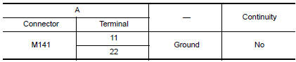
- Check continuity between display unit harness connector M141 (A) terminals 11, 22 and ground.
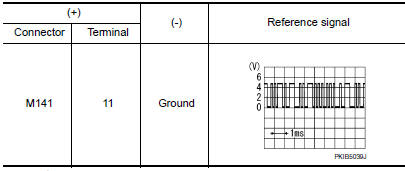
3.CHECK COMMUNICATION SIGNAL
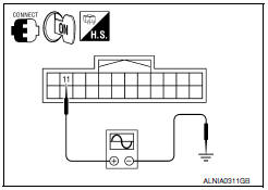
- Connect display unit connector and AV control unit connector.
- Turn ignition switch ON.
- Check signal between display unit harness connector M141 terminal 11 and ground with an oscilloscope or CONSULT.
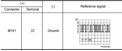
4.CHECK COMMUNICATION SIGNAL
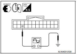
Check signal between display unit harness connector M141 terminal 22 and ground with an oscilloscope or CONSULT.
 U1232 steering angle sensor
DTC Logic
Diagnosis Procedu
1.ADJUST THE PREDICTIVE COURSE LINE CENTER POSITION OF THE STEERING ANGLE
SENSOR
When U1232 is detected, adjust the predictive course line center position of
the ...
 U1263 USB
DTC Logic
Diagnosis Procedure
1.CHECK USB HARNESS
Visually check USB harness. ...
Other materials:
Normal operating condition
Description
The majority of the audio concerns are the result of outside causes (bad CD,
electromagnetic interference,
etc.).
NOISE
The following noise results from variations in field strength, such as fading
noise and multi-path noise, or
external noise from trains and other sources. I ...
Optical sensor
Exploded View
Optical sensor
LH front tweeter speaker grille
Optical sensor harness connector
LH front tweeter speaker
Instrument panel
Removal and Installation
CAUTION: Whenever a suitable tool is used,
always wrap a cloth around the end of the tool to protect components from ...
Indicator lights
For additional information, refer to "Vehicle information
display" in this section.
Front fog light indicator
light
(green)
The front fog light indicator light illuminates when
the front fog lights are on. For additional information,
refer to "Fog light switch" in this section.
Front passen ...
Nissan Maxima Owners Manual
- Illustrated table of contents
- Safety-Seats, seat belts and supplemental restraint system
- Instruments and controls
- Pre-driving checks and adjustments
- Monitor, climate, audio, phone and voice recognition systems
- Starting and driving
- In case of emergency
- Appearance and care
- Do-it-yourself
- Maintenance and schedules
- Technical and consumer information
Nissan Maxima Service and Repair Manual

0.0063