Nissan Maxima Service and Repair Manual: Climate controlled seat switch indicator
Description
Illuminates the climate controlled seat switch to indicate operating status.
Component Function Check
1.CHECK CLIMATE CONTROLLED SEAT SWITCH INDICATOR FUNCTION
Check that the indicators for the climate controlled seat switch operate in both COOL and HEAT modes.
Diagnosis Procedure
Regarding Wiring Diagram information, refer to SE-44, "Wiring Diagram".
1.CHECK CLIMATE CONTROLLED SEAT SWITCH INDICATOR
Perform climate controlled seat switch indicator component inspection. Refer to SE-24, "Component Inspection (Climate Controlled Seat Switch Indicator)".
2.CHECK CLIMATE CONTROLLED SEAT SWITCH COOL INDICATOR CIRCUIT
- Turn ignition switch OFF.
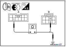
- Disconnect climate controlled seat switch connector and climate controlled seat control unit connector B216.
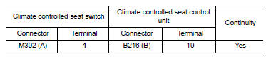
- Check continuity between climate controlled seat switch connector M302 (A) terminal 4 and climate controlled seat control unit connector B216 (B) terminal 19.
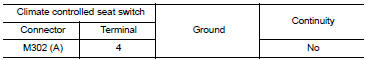
4. Check continuity between climate controlled seat switch connector M302 (A) terminal 4 and ground.
3.CHECK CLIMATE CONTROLLED SEAT SWITCH HEAT INDICATOR CIRCUIT
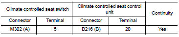
1. Check continuity between climate controlled seat switch connector M302 (A) terminal 5 and climate controlled seat control unit connector B216 (B) terminal 20.
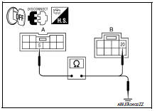
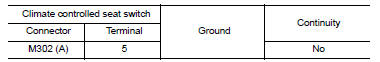
2. Check continuity between climate controlled seat switch connector M302 (A) terminal 5 and ground.
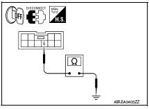
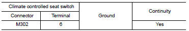
4.CHECK CLIMATE CONTROLLED SEAT SWITCH INDICATOR GROUND CIRCUIT
Check continuity between climate controlled seat switch connector M302 terminal 6 and ground.
Component Inspection (Climate Controlled Seat Switch Indicator)
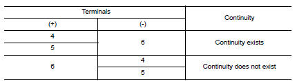
1.CHECK CLIMATE CONTROLLED SEAT SWITCH
- Disconnect climate controlled seat switch connector.
- Check continuity between climate controlled seat switch terminals.
 Climate controlled seat switch
Description
Provides inputs to the climate controlled seat control unit for climate
controlled seat operation.
Component Function Check
1.CHECK CLIMATE CONTROLLED SEAT SWITCH FUNCTION
Turn the c ...
 ECU diagnosis information
CLIMATE CONTROLLED SEAT CONTROL UNIT
Reference Value
TERMINAL LAYOUT
PHYSICAL VALUES
Fail-safe
Climate controlled seat control unit equips fail-safe function.
When a malfunction occurs ...
Other materials:
P0605 ECM
Description
The ECM consists of a microcomputer and connectors for signal
input and output and for power supply. The ECM controls the engine
DTC Logic
DTC DETECTION LOGIC
DTC CONFIRMATION PROCEDURE
1.PRECONDITIONING
If DTC Confirmation Procedure has been previously conducted, always ...
Daytime running light system
The LED portion of the headlights automatically
illuminate at 100% intensity when the engine is
started and the parking brake released. The daytime
running lights operate with the headlight
switch in the OFF position. When you turn the
headlight switch to the position for
full
illumination t ...
System temporarily unavailable
When radar blockage is detected, the system will
be deactivated automatically. The "Side Radar
Obstruction" warning message will appear and
the BSW/RCTA indicator (white) will blink A in
the vehicle information display.
The system is not available until the conditions no
longer exist.
...
Nissan Maxima Owners Manual
- Illustrated table of contents
- Safety-Seats, seat belts and supplemental restraint system
- Instruments and controls
- Pre-driving checks and adjustments
- Monitor, climate, audio, phone and voice recognition systems
- Starting and driving
- In case of emergency
- Appearance and care
- Do-it-yourself
- Maintenance and schedules
- Technical and consumer information
Nissan Maxima Service and Repair Manual

0.0053