Nissan Maxima Service and Repair Manual: Key cylinder switch
Description
The main power window and door lock/unlock switch detects condition of the door key cylinder switch and transmits to BCM as the LOCK or UNLOCK signal.
Component Function Check
1. CHECK DOOR KEY CYLINDER SWITCH INPUT SIGNAL
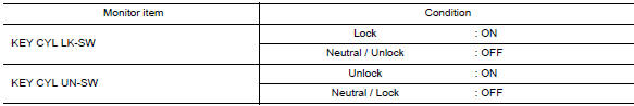
Check KEY CYL UN-SW, KEY CYL UN-SW in "DATA MONITOR" mode for "POWER DOOR LOCK SYSTEM" with CONSULT.
Diagnosis Procedure
1. CHECK DOOR KEY CYLINDER SWITCH INPUT SIGNAL
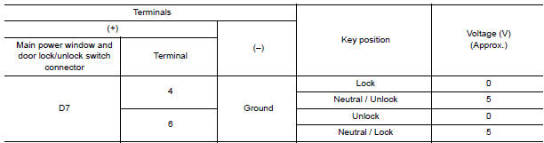
- Turn ignition switch ON.
- Check voltage between main power window and door lock/unlock switch connector and ground.
2. CHECK DOOR KEY CYLINDER SIGNAL CIRCUIT
- Turn ignition switch OFF.
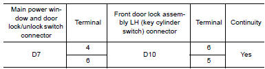
- Disconnect main power window and door lock/unlock switch connector and front door lock assembly LH (key cylinder switch) connector.
- Check continuity between main power window and door lock/unlock switch connector and front door lock assembly LH (key cylinder switch) connector.
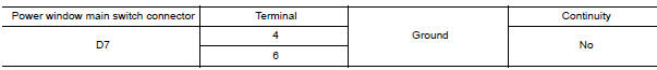
- Check continuity between main power window and door lock/unlock switch connector and ground
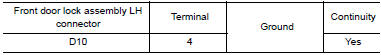
3. CHECK DOOR KEY CYLINDER SWITCH GROUND CIRCUIT
Check continuity between front door lock assembly LH connector and ground.
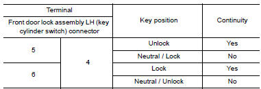
4. CHECK DOOR KEY CYLINDER SWITCH
Check door key cylinder switch
Component Inspection
COMPONENT INSPECTION
1. CHECK DOOR KEY CYLINDER SWITCH
Check front door lock assembly LH (key cylinder switch).
Special Repair Requirement
1. PERFORM INITIALIZATION PROCEDURE
Perform initialization procedure.
 Key slot
Description
Detects whether Intelligent Key is inserted.
Immobilizer antenna amp checks Intelligent Key transponder.
Component Function Check
1. CHECK FUNCTION
With CONSULT
Check KEY SW -SLO ...
 Unlock sensor
Description
Detects door lock condition of driver door.
Component Function Check
1. CHECK FUNCTION
With CONSULT
Check unlock sensor UNLK SEN−DR in "Data Monitor" mode.
Diagnosis Proc ...
Other materials:
Power seat switch ground circuit
Diagnosis Procedure
1. CHECK POWER SEAT SWITCH LH GROUND CIRCUIT
Turn ignition switch OFF.
Disconnect power seat switch LH.
Check continuity between power seat switch LH connector and
ground.
...
Environmental factors influence the rate of corrosion
Moisture
Accumulation of sand, dirt and water on the vehicle
body underside can accelerate corrosion.
Wet floor coverings will not dry completely inside
the vehicle and should be removed for drying to
avoid floor panel corrosion.
Relative humidity
Corrosion will be accelerated in areas of h ...
Symptom diagnosis
REFRIGERATION SYSTEM SYMPTOMS
WITH COLOR DISPLAY
WITH COLOR DISPLAY : Trouble Diagnoses for Abnormal Pressure
Whenever system′s high and/or low side pressure is abnormal, diagnose using a
manifold gauge. The marker above the gauge scale in the following tables
indicates the standard (us ...
Nissan Maxima Owners Manual
- Illustrated table of contents
- Safety-Seats, seat belts and supplemental restraint system
- Instruments and controls
- Pre-driving checks and adjustments
- Monitor, climate, audio, phone and voice recognition systems
- Starting and driving
- In case of emergency
- Appearance and care
- Do-it-yourself
- Maintenance and schedules
- Technical and consumer information
Nissan Maxima Service and Repair Manual

0.0057