Nissan Maxima Service and Repair Manual: Parking brake switch signal circuit
Description
Transmits the parking brake switch signal to the combination meter.
Component Function Check
1.COMBINATION METER INPUT SIGNAL
-
Select "METER/M&A" on CONSULT.
-
Monitor "PKB SW" of "DATA MONITOR" while applying and releasing the parking brake.
>> Inspection End.
Diagnosis Procedure
Regarding Wiring Diagram information, refer to MWI-87, "Wiring Diagram".
1.CHECK PARKING BRAKE SWITCH CIRCUIT
-
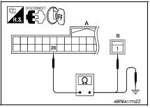
Disconnect combination meter connector and parking brake switch connector.
-
Check continuity between combination meter harness connector M24 (A) terminal 26 and parking brake switch harness connector E35 (B) terminal 1.
3. Check continuity between combination meter harness connector M24 (A) terminal 26 and ground.
Component Inspection
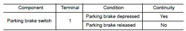
1.CHECK PARKING BRAKE SWITCH
Check continuity between parking brake switch terminal 1 and switch case ground.
 Oil pressure switch signal circuit
Description
Detects the engine oil pressure and transmits the oil
pressure switch signal to the IPDM E/R.
Component Function Check
1.COMBINATION METER INPUT SIGNAL
Select "METER/M&am ...
 Washer level switch signal circuit
Description
Transmits the washer fluid level switch signal to the
combination meter.
Component Function Check
1.COMBINATION METER INPUT SIGNAL
Select "METER/M&A" on CONSULT.
...
Other materials:
EVAP control system pressure sensor
Removal and Installation
REMOVAL
Remove rear stabilizer bar clamps and position rear stabilizer bar
aside. Refer to RSU-13, "Removal and Installation".
Disconnect EVAP hose from EVAP canister.
Disconnect EVAP control system pressure sensor.
Remove EVAP control s ...
Front door speaker
Removal and Installation
REMOVAL
Remove the front door finisher. Refer to INT-18, "Removal and
Installation".
Remove the front door speaker screws (A).
Disconnect the harness connector from the front door speaker
(1) and remove.
Remove the front door speaker spacer scr ...
P2100, P2103 throttle control motor relay
Description
Power supply for the throttle control motor is provided to the ECM via the
throttle control motor relay. The throttle
control motor relay is controlled ON/OFF by the ECM. When the ignition switch is
turned ON, the ECM
sends an ON signal to throttle control motor relay and batter ...
Nissan Maxima Owners Manual
- Illustrated table of contents
- Safety-Seats, seat belts and supplemental restraint system
- Instruments and controls
- Pre-driving checks and adjustments
- Monitor, climate, audio, phone and voice recognition systems
- Starting and driving
- In case of emergency
- Appearance and care
- Do-it-yourself
- Maintenance and schedules
- Technical and consumer information
Nissan Maxima Service and Repair Manual

0.0075