Nissan Maxima Service and Repair Manual: Washer level switch signal circuit
Description
Transmits the washer fluid level switch signal to the combination meter.
Component Function Check
1.COMBINATION METER INPUT SIGNAL
-
Select "METER/M&A" on CONSULT.
-
Monitor "WASHER W/L" of "DATA MONITOR" under the following conditions.
>> Inspection End.
Diagnosis Procedure
Regarding Wiring Diagram information, refer to MWI-87, "Wiring Diagram".
1.CHECK WASHER FLUID LEVEL SWITCH SIGNAL CIRCUIT
-
Turn ignition switch OFF.
-
Disconnect combination meter connector and washer fluid level switch connector.
-
Check continuity between combination meter harness connector M24 (A) terminal 29 and washer fluid level switch harness connector E208 (B) terminal 1.
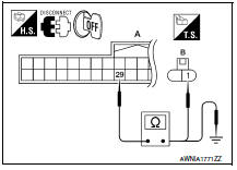
4. Check continuity between combination meter harness connector M24 (A) terminal 29 and ground.
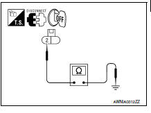
2.CHECK WASHER FLUID LEVEL SWITCH GROUND CIRCUIT
Check continuity between washer fluid level switch harness connector E208 terminal 2 and ground.
Component Inspection
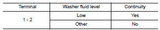
1.CHECK WASHER FLUID LEVEL SWITCH
Check continuity between washer fluid level switch terminals 1 and 2.
 Parking brake switch signal circuit
Description
Transmits the parking brake switch signal to the
combination meter.
Component Function Check
1.COMBINATION METER INPUT SIGNAL
Select "METER/M&A" on CONSULT.
& ...

Other materials:
Locking with power door lock switch
To lock all the doors without a key, push the door
lock switch (driver's or front passenger's side) to
the lock position 1 . When locking the door this
way, be certain not to leave the key inside the
vehicle.
To unlock all the doors without a key, push the
door lock switch (driver's or f ...
Precaution
PRECAUTIONS
Precaution for Supplemental Restraint System (SRS) "AIR BAG" and
"SEAT BELT PRE-TENSIONER"
The Supplemental Restraint System such as "AIR BAG" and "SEAT BELT
PRE-TENSIONER", used along with a front seat belt, helps to reduce the risk
or severity of injury to the driver and front ...
Multi AV system symptoms
Symptom Table
RELATED TO NAVIGATION
Trouble Diagnosis Chart by Symptom
RELATED TO HANDS-FREE PHONE
Before performing diagnosis, confirm that the cellular phone being
used by the customer is compatible with
the vehicle.
It is possible that a malfunction is occurring due to a versio ...
Nissan Maxima Owners Manual
- Illustrated table of contents
- Safety-Seats, seat belts and supplemental restraint system
- Instruments and controls
- Pre-driving checks and adjustments
- Monitor, climate, audio, phone and voice recognition systems
- Starting and driving
- In case of emergency
- Appearance and care
- Do-it-yourself
- Maintenance and schedules
- Technical and consumer information
Nissan Maxima Service and Repair Manual

0.0073