Nissan Maxima Service and Repair Manual: Oil pressure switch signal circuit
Description
Detects the engine oil pressure and transmits the oil pressure switch signal to the IPDM E/R.
Component Function Check
1.COMBINATION METER INPUT SIGNAL
-
Select "METER/M&A" on CONSULT.
-
Monitor "OIL W/L" of "DATA MONITOR" while operating ignition switch.
>> Inspection End.
Diagnosis Procedure INFOID:0000000010049589
Regarding Wiring Diagram information, refer to MWI-87, "Wiring Diagram".
1.CHECK OIL PRESSURE SWITCH CIRCUIT
-
Turn ignition switch OFF.
-
Disconnect IPDM E/R connector F10 and oil pressure switch connector F41.
-
Check continuity between IPDM E/R harness connector F10 terminal 75 and oil pressure switch harness connector F41 terminal 1.
-
Check continuity between IPDM E/R harness connector F10 terminal 75 and ground.
Component Inspection
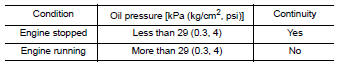
1.CHECK OIL PRESSURE SWITCH
Check continuity between oil pressure switch and ground.
 Fuel level sensor signal circuit
Description
The fuel level sensor unit and fuel pump (fuel level
sensor) detects the approximate fuel level in the fuel tank
and transmits the fuel level signal to the combination meter.
Compone ...
 Parking brake switch signal circuit
Description
Transmits the parking brake switch signal to the
combination meter.
Component Function Check
1.COMBINATION METER INPUT SIGNAL
Select "METER/M&A" on CONSULT.
& ...
Other materials:
Disk eject signal circuit
Description
The eject signal is output to AV control unit when the eject switch of A/C
and AV switch assembly is pressed.
Diagnosis Procedure
1.CHECK CONTINUITY DISK EJECT SIGNAL CIRCUIT
Turn ignition switch OFF.
Disconnect A/C and AV switch assembly connector M98 and AV
control un ...
Vehicle information display warnings and indicators
No Key Detected
Key ID Incorrect
Key Battery Low
I-Key System Error: See Owner's Manual
Shift to Park
Push brake and start switch to drive
Engine start operation for Intelligent Key system
(if I-Key battery level is low)
Release Parking Brake
Low Fuel
Low Washer Fluid
Ti ...
Headlamp
Wiring Diagram
...
Nissan Maxima Owners Manual
- Illustrated table of contents
- Safety-Seats, seat belts and supplemental restraint system
- Instruments and controls
- Pre-driving checks and adjustments
- Monitor, climate, audio, phone and voice recognition systems
- Starting and driving
- In case of emergency
- Appearance and care
- Do-it-yourself
- Maintenance and schedules
- Technical and consumer information
Nissan Maxima Service and Repair Manual

0.0062