Nissan Maxima Service and Repair Manual: Fuel level sensor signal circuit
Description
The fuel level sensor unit and fuel pump (fuel level sensor) detects the approximate fuel level in the fuel tank and transmits the fuel level signal to the combination meter.
Component Function Check
1.COMBINATION METER INPUT SIGNAL
-
Select "METER/M&A" on CONSULT.
-
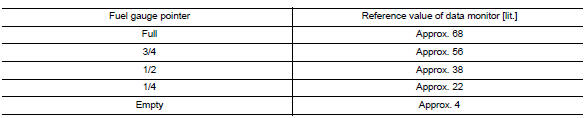
Using "FUEL METER" of "DATA MONITOR", compare the value of DATA MONITOR with fuel gauge pointer of combination meter.
Diagnosis Procedure
Regarding Wiring Diagram information, refer to MWI-87, "Wiring Diagram".
1.CHECK HARNESS CONNECTOR
-
Turn ignition switch OFF.
-
Check combination meter and fuel level sensor unit and fuel pump (fuel level sensor) terminals (meterside and harness-side) for poor connection.
2.CHECK FUEL LEVEL SENSOR UNIT AND FUEL PUMP (FUEL LEVEL SENSOR) CIRCUIT
-
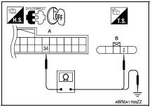
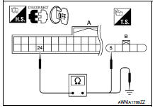
Disconnect combination meter connector and fuel level sensor unit and fuel pump (fuel level sensor) connector.
-
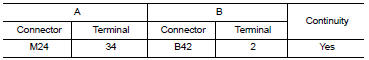
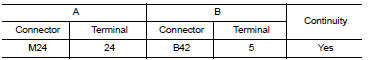
Check continuity between combination meter harness connector (A) and fuel level sensor unit and fuel pump (fuel level sensor) harness connector (B).
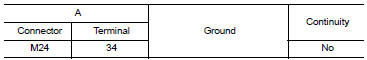
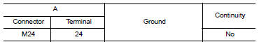
3. Check continuity between combination meter harness connector (A) and ground.
3.CHECK FUEL LEVEL SENSOR UNIT AND FUEL PUMP (FUEL LEVEL SENSOR) GROUND CIRCUIT
1. Check continuity between combination meter harness connector (A) and fuel level sensor unit and fuel pump (fuel level sensor) harness connector (B).
2. Check continuity between combination meter harness connector (A) and ground.
4.CHECK INSTALLATION CONDITION
Check fuel level sensor unit and fuel pump (fuel level sensor) installation, and check whether the float arm interferes or binds with any of the internal components in the fuel tank.
Component Inspection
1.REMOVE FUEL LEVEL SENSOR UNIT AND FUEL PUMP (FUEL LEVEL SENSOR)
Remove the fuel level sensor unit and fuel pump (fuel level sensor). Refer to FL-6, "Removal and Installation".
>> GO TO 2
2.CHECK FUEL LEVEL SENSOR UNIT AND FUEL PUMP (FUEL LEVEL SENSOR)
Check the resistance between terminals 2 and 5.
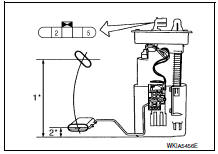
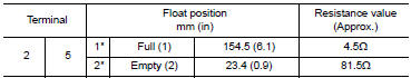
1* and 2*: When float arm is in contact with stopper.
 Power supply and ground circuit
COMBINATION METER
COMBINATION METER : Diagnosis Procedure
Regarding Wiring Diagram information, refer to MWI-87, "Wiring Diagram".
1.CHECK FUSES
Check for blown combination meter fuses.
2.POWER ...
 Oil pressure switch signal circuit
Description
Detects the engine oil pressure and transmits the oil
pressure switch signal to the IPDM E/R.
Component Function Check
1.COMBINATION METER INPUT SIGNAL
Select "METER/M&am ...
Other materials:
P1564 ASCD steering switch
Description
ASCD steering switch has variant values of electrical resistance for each
button. ECM reads voltage variation
of switch, and determines which button is operated.
Refer to EC-68, "System Diagram" for the ASCD function.
DTC Logic
DTC DETECTION LOGIC
NOTE:
If DTC P156 ...
Unit disassembly and assembly
COMBINATION METER
Disassembly and Assembly
DISASSEMBLY
Remove the combination meter. Refer to MWI-122,
"Removal and Installation".
Remove the combination meter lens (1) from the
combination
meter (2).
ASSEMBLY
Assembly is in the reverse order of disasse ...
Glove box
Open the glove box by pulling the handle. Use the
master key when locking or unlocking the glove
box.
There is a trunk cancel switch in the glove box.
For additional information, refer to "Cancel
switch" in the "Pre-driving checks and adjustments"
section of this manual.
WARNING
Keep g ...
Nissan Maxima Owners Manual
- Illustrated table of contents
- Safety-Seats, seat belts and supplemental restraint system
- Instruments and controls
- Pre-driving checks and adjustments
- Monitor, climate, audio, phone and voice recognition systems
- Starting and driving
- In case of emergency
- Appearance and care
- Do-it-yourself
- Maintenance and schedules
- Technical and consumer information
Nissan Maxima Service and Repair Manual

0.0062