Nissan Maxima Owners Manual: Front and Rear Sonar System (if so equipped)
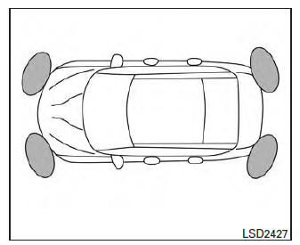
The sonar (parking sensor) system sounds a tone to inform the driver of obstacles near the bumper.
When the "DISPLAY" key is ON, the sonar view will automatically appear in the meter.
WARNING
- The sonar (parking sensor) system is a convenience but it is not a substitute for proper parking.
- The driver is always responsible for
safety during parking and other maneuvers.
Always look around and check that it is safe to do so before parking.
- Read and understand the limitations of the sonar (parking sensor) system as contained in this section. The colors of the corner sonar indicator and the distance guide lines in the front/rear view indicate different distances to the object.
- Inclement weather or ultrasonic sources such as an automatic car wash, a truck's compressed-air brakes or a pneumatic drill may affect the function of the system; this may include reduced performance or a false activation.
- This function is designed as an aid to the driver in detecting large stationary objects to help avoid damaging the vehicle.
- The system is not designed to prevent
contact with small or moving objects.
Always move slowly. The system will not detect small objects below the bumper, and may not detect objects close to the bumper or on the ground.
- The system may not detect the following objects: Fluffy objects such as snow, cloth, cotton, glass, wool, etc., Thin objects such as rope, wire and chain, etc., or wedge-shaped objects.
If your vehicle sustains damage to the bumper fascia, leaving it misaligned or bent, the sensing zone may be altered causing inaccurate measurement of obstacles or false alarms.
CAUTION
- Excessive noise (such as audio system volume or an open vehicle window) will interfere with the tone and it may not be heard.
- Keep the sonar sensors (located on the bumper fascia) free from snow, ice and large accumulations of dirt. Do not clean the sensors with sharp objects. If the sensors are covered, the accuracy of the sonar function will be diminished.
System operation
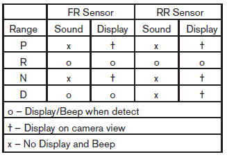
The system informs with a visual and audible alert of front obstacles when the shift lever is in the D (Drive) position and both front and rear obstacles when the shift lever is in the R (Reverse) position.
Sonar Operation Table
The system is deactivated at speeds above 6 mph (10 km/h). It is reactivated at lower speeds.
The intermittent tone will stop after 3 seconds when an obstacle is detected by only the corner sensor and the distance does not change. The tone will stop when the obstacle get away from the vehicle.
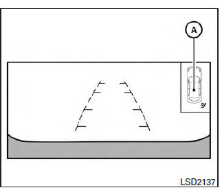
When the object is detected, the indicator (green) appears and blinks and the tone sounds intermittently. When the vehicle moves closer to the object, the color of the indicator turns yellow and the rate of the blinking increase. When the vehicle is very close to the object, the indicator stops blinking and turns red, and the tone sounds continuously.
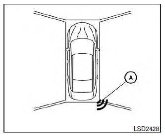
When the corner of the vehicle moves closer to an object, the corner sonar indicator A appears.
The system indicators A will appear when the vehicle moves closer to an object.
 Active ride control
This system senses upper body motion (based
on wheel speed information) and controls engine
torque and four wheel brake pressure. This will
enhance ride comfort in effort to restrain uncomfortable
...

Other materials:
Diagnosis and repair workflow
Work Flow
OVERALL SEQUENCE
DETAILED FLOW
1. GET INFORMATION FOR SYMPTOM
Get the detailed information from the customer about the symptom (the
condition and the environment when
the incident/malfunction occurred).
2. CHECK DTC
Check DTC.
Perform the following procedure if DTC is ...
Air bags, seat belts and child restraints
Top tether strap anchor
Rear head restraints/headrests
Rear seat belts
Roof-mounted curtain side-impact and
rollover supplemental air bag
Front seat-mounted side-impact
supplemental air bags
Front head restraints/headrests
Front seat belt with pretensioner(s) and
shoulder he ...
Signal buffer system
System Diagram
System Description
OUTLINE
BCM has the signal transmission function that outputs/transmits each
input/received signal to each unit.
Signal transmission function list
Signal name
Input
Output
Description
Ignition switch ON si ...
Nissan Maxima Owners Manual
- Illustrated table of contents
- Safety-Seats, seat belts and supplemental restraint system
- Instruments and controls
- Pre-driving checks and adjustments
- Monitor, climate, audio, phone and voice recognition systems
- Starting and driving
- In case of emergency
- Appearance and care
- Do-it-yourself
- Maintenance and schedules
- Technical and consumer information
Nissan Maxima Service and Repair Manual

0.0063