Nissan Maxima Service and Repair Manual: Main power window and door lock/unlock switch
Removal and Installation
REMOVAL
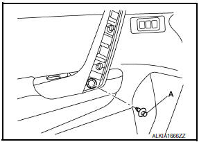
- Remove the front door grip cover. Refer to DLK-214, "FRONT DOOR : Removal and Installation".
- Remove the clip (A) from the door grip using a suitable tool.
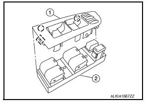
- Release the metal clip and lift the main power window and door
lock/unlock switch (2) and finisher (1) as an assembly starting
from the rear using a suitable tool, pull upward to remove it from
the front door finisher.
 : Metal clip
 - Disconnect the harness connector from the main power window and door lock/unlock switch.
- Release the pawls on each side to separate the switch finisher
(1) from the main power window and door lock/unlock switch (2).
 : Pawl
CAUTION: Do not damage the pawl of the switch finisher.
INSTALLATION
Installation is in the reverse order of removal.
NOTE: Whenever the main power window and door lock/unlock switch is disconnected from the harness connector, it is necessary to perform the Initialization procedure.

 Power window and door lock/unlock switch RH
Removal and Installation
REMOVAL
Remove the front door grip cover. Refer to INT-18, "Removal and
Installation".
Remove the clip (A) from the door grip using suitable tool.
...
Other materials:
ADP branch line circuit
Diagnosis Procedure
1.CHECK CONNECTOR
Turn the ignition switch OFF.
Disconnect the battery cable from the negative terminal.
Check the following terminals and connectors for damage, bend and
loose connection (unit side and connector
side).
Driver seat control unit
Harness connec ...
U1010 control unit (CAN)
Description
Refer to LAN-24, "CAN Communication Signal Chart".
DTC Logic
DTC DETECTION LOGIC
DTC No.
Trouble diagnosis name
DTC detecting condition
Possible cause
U1010
CONTROL UNIT (CAN
When detecting error during the initial diagnosis of CAN controller
of dri ...
Basic inspection
DIAGNOSIS AND REPAIR WORKFLOW
Work Flow
OVERALL SEQUENCE
DETAILED FLOW
1. GET INFORMATION FOR SYMPTOM
Get the detailed information from the customer about the symptom (the
condition and the environment when
the incident/malfunction occurred).
2. CHECK DTC
Check DTC.
Perform the f ...
Nissan Maxima Owners Manual
- Illustrated table of contents
- Safety-Seats, seat belts and supplemental restraint system
- Instruments and controls
- Pre-driving checks and adjustments
- Monitor, climate, audio, phone and voice recognition systems
- Starting and driving
- In case of emergency
- Appearance and care
- Do-it-yourself
- Maintenance and schedules
- Technical and consumer information
Nissan Maxima Service and Repair Manual

0.0051