Nissan Maxima Service and Repair Manual: Power window and door lock/unlock switch RH
Removal and Installation
REMOVAL
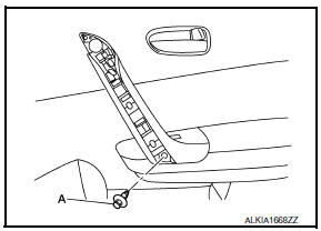
- Remove the front door grip cover. Refer to INT-18, "Removal and Installation".
- Remove the clip (A) from the door grip using suitable tool.
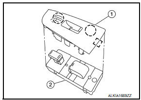
- Release the metal clip and lift the power window and door lock/
unlock switch (2) and switch finisher (1) as an assembly starting
from the rear using a suitable tool, pull upward to remove it from
the front door finisher.
 : Metal clip
 - Disconnect the harness connector from the power window and door lock/unlock switch.
- Release the pawls on each side to separate the switch finisher
(1) from the power window and door lock/unlock switch (2).
 : Pawl
CAUTION: Do not damage the pawl of the switch finisher.
INSTALLATION Installation is in the reverse order of removal.
NOTE: Whenever the power window and door lock/unlock switch is disconnected from the harness connector, it is necessary to perform the Initialization procedure.
 Main power window and door lock/unlock switch
Removal and Installation
REMOVAL
Remove the front door grip cover. Refer to DLK-214, "FRONT DOOR :
Removal and Installation".
Remove the clip (A) from the door grip using a suitabl ...
 Rear power window switch
Removal and Installation
REMOVAL
Remove the rear door armrest finisher. Refer to INT-21,
"Removal and Installation".
Release the pawls on each side to separate the switch finis ...
Other materials:
Line pressure test
Inspection and Judgment
INSPECTION
Line Pressure Test Procedure
Inspect the amount of engine oil and replenish
if necessary.
Drive the car for about 10 minutes to warm it
up so that the CVT fluid reaches in the range of 50 to 80C
(122 to 176F). Then inspect the ...
Diagnosis system (meter)
Diagnosis Description
SELF-DIAGNOSIS MODE
Odo/trip meter and information display segment operation can be
checked in self-diagnosis mode.
Meters/gauges can be checked in self-diagnosis mode.
OPERATION PROCEDURE
Turn the ignition switch OFF.
While pushing the odo/trip meter switch, ...
Sunroof switch
Description
Transmits switch operation signal to sunroof motor assembly.
Diagnosis Procedure
1.CHECK SUNROOF SWITCH INPUT SIGNAL
Turn ignition switch ON.
Check voltage between sunroof motor assembly harness connector
and ground.
2.CHECK SUNROOF SWITCH CIRCUIT
Turn ...
Nissan Maxima Owners Manual
- Illustrated table of contents
- Safety-Seats, seat belts and supplemental restraint system
- Instruments and controls
- Pre-driving checks and adjustments
- Monitor, climate, audio, phone and voice recognition systems
- Starting and driving
- In case of emergency
- Appearance and care
- Do-it-yourself
- Maintenance and schedules
- Technical and consumer information
Nissan Maxima Service and Repair Manual

0.0085