Nissan Maxima Service and Repair Manual: Rear power window switch
Removal and Installation
REMOVAL
- Remove the rear door armrest finisher. Refer to INT-21, "Removal and Installation".
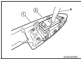
- Release the pawls on each side to separate the switch finisher
(1) from the rear power window switch (2) using a suitable tool
(A).
 : Pawl
INSTALLATION
Installation is in the reverse order of removal.
 Power window and door lock/unlock switch RH
Removal and Installation
REMOVAL
Remove the front door grip cover. Refer to INT-18, "Removal and
Installation".
Remove the clip (A) from the door grip using suitable tool.
...
 Roof
Roof
...
Other materials:
Satellite radio antenna
Removal and Installation
REMOVAL
Lower the headlining at the rear. Refer to INT-33, "Exploded
View".
Disconnect the harness connector (A) from satellite radio
antenna.
Remove the satellite radio antenna nut (B) and the satellite radio
antenna (1).
INSTALLATION
Installation is ...
Programming HomeLink for Canadian customers and gate openers
Canadian radio-frequency laws require transmitter
signals to "time-out" (or quit) after several
seconds of transmission - which may not be long
enough for HomeLink to pick up the signal
during training. Similar to this Canadian law,
some U.S. gate operators are designed to "timeout"
in the sam ...
Clip list
Descriptions for Clips
Replace any clips which are damaged during removal or installation.
...
Nissan Maxima Owners Manual
- Illustrated table of contents
- Safety-Seats, seat belts and supplemental restraint system
- Instruments and controls
- Pre-driving checks and adjustments
- Monitor, climate, audio, phone and voice recognition systems
- Starting and driving
- In case of emergency
- Appearance and care
- Do-it-yourself
- Maintenance and schedules
- Technical and consumer information
Nissan Maxima Service and Repair Manual

0.006