Nissan Maxima Service and Repair Manual: Audio system
System Diagram
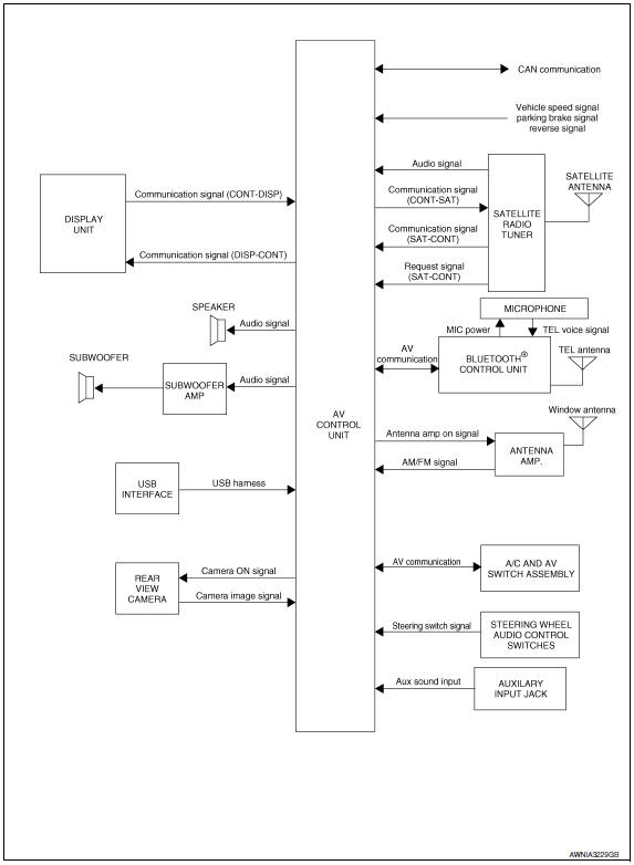
System Description
AUDIO SYSTEM
The audio system consists of the following components
- AV control unit
- Display unit
- Window antenna
- Steering wheel audio control switches
- A/C and AV switch assembly
- Front door speakers
- Tweeters
- Rear door speakers
- Subwoofers
When the audio system is on, radio signals are received by the window antenna. The AV control unit then sends audio signals to the front door speakers, tweeters, rear door speakers, subwoofer amp. and subwoofers.
Refer to Owner's Manual for audio system operating instructions.
SATELLITE RADIO SYSTEM
The satellite radio system consists of the following components
- Satellite antenna
- Satellite radio tuner
When the satellite radio system is on, radio signals are supplied to the satellite radio tuner from the satellite antenna. The satellite radio tuner then sends audio signals to the AV control unit.
Refer to Owner's Manual for satellite radio system operating instructions.
SPEED SENSITIVE VOLUME SYSTEM
Volume level of this system goes up and down automatically in proportion to the vehicle speed. The control level can be selected by the customer. Refer to Owner's Manual for operating instructions.
Component Parts Location
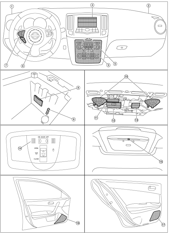
- Tweeter LH M143
- Tweeter RH M144
- AV control unit M115, M116, M117, M118, M119, M120, M121 (located behind A/C and AV switch assembly)
- Display unit M141
- A/C and AV switch assembly M98
- Steering angle sensor M53 [located in steering column behind combination switch (spiral cable)]
- Steering wheel audio control switches
- USB interface M211 (view in center console)
- Aux jack M209
- Subwoofer (view under rear parcel shelf) LH B16 RH B17
- Satellite radio tuner B111
- Bluetooth control unit B125, B130, B131
- Subwoofer amp. B21
- Microphone R7
- Rear view camera T101
- Front door speaker LH D3 RH D103
- Rear door speaker LH D202 RH D302
Component Description
| Part name | Description |
| AV control unit | Controls audio system, USB connection, AUX IN connection and satellite radio system |
| Display unit | Displays all audio and climate control related inform |
| Steering wheel audio control switches |
|
| Front door speakers |
|
| Tweeters |
|
| Rear door speakers |
|
| Subwoofer amp |
|
| Subwoofers |
|
| Satellite radio tuner |
|
| Satellite antenna | Audio signal (satellite radio) is received and output to AV control
unit.
Revision: August |

 Rear view monitor system
System Diagram
System Description
When the shift selector is in the R position, the display shows a view to the
rear of the vehicle. Lines which indicate the vehicle clearance and distances
ar ...
Other materials:
B2581, B2582 intake sensor
Description
Intake Sensor
The intake sensor is located on the evaporator.
It converts air temperature after it passes through the evaporator
into a resistance value which is then input to the A/C auto amp.
Intake Sensor Circuit
DTC Logic
DTC DETECTION LOGIC
NOTE:
If DTC is di ...
P0460 fuel level sensor
Description
The fuel level sensor is mounted in the fuel level sensor unit.
The sensor detects a fuel level in the fuel tank and transmits a signal to the
combination meter. The combination
meter sends the fuel level sensor signal to the ECM via the CAN communication
line.
It consists o ...
Multi AV system symptoms
Symptom Table
RELATED TO NAVIGATION
Trouble Diagnosis Chart by Symptom
RELATED TO HANDS-FREE PHONE
Before performing diagnosis, confirm that the cellular phone being
used by the customer is compatible with
the vehicle.
It is possible that a malfunction is occurring due to a versio ...
Nissan Maxima Owners Manual
- Illustrated table of contents
- Safety-Seats, seat belts and supplemental restraint system
- Instruments and controls
- Pre-driving checks and adjustments
- Monitor, climate, audio, phone and voice recognition systems
- Starting and driving
- In case of emergency
- Appearance and care
- Do-it-yourself
- Maintenance and schedules
- Technical and consumer information
Nissan Maxima Service and Repair Manual

0.0061