Nissan Maxima Service and Repair Manual: P0710 transmission fluid temperature sensor A
Description
The CVT fluid temperature sensor detects the CVT fluid temperature and sends a signal to the TCM.
DTC Logic
DTC DETECTION LOGIC
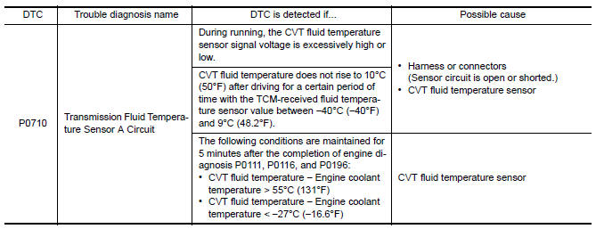
DTC CONFIRMATION PROCEDURE
CAUTION: Always drive vehicle at a safe speed.
NOTE: Immediately after performing any "DTC CONFIRMATION PROCEDURE", always turn ignition switch OFF.
Then wait at least 10 seconds before performing the next test.
1.CHECK DTC DETECTION (PART 1)
- Start the engine.
- Maintain the following condition for 5 seconds or more.
- Stop the vehicle.
- Check the first trip DTC.
2.CHECK DTC DETECTION (PART 2)
 With CONSULT
- Turn ignition switch OFF and cool the engine.
- Turn ignition switch ON.
CAUTION: Never start the engine.
- Select "Data Monitor" in "TRANSMISSION".
- Select "FLUID TEMP".
- Record CVT fluid temperature.
- Start the engine and wait for at least 2 minutes.
- Drive the vehicle for the total minutes specified in the Driving time column below with the following conditions satisfied.
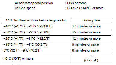
8. Stop the vehicle.
9. Check the first trip DTC.
 With GST
- Turn ignition switch OFF and cool the engine.
- Start the engine and wait for at least 2 minutes.
- Drive the vehicle and maintain the following conditions for 17 minutes or more.
- Stop the vehicle.
- Check the first trip DTC.
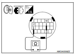
3.CHECK CVT FLUID TEMPERATURE SENSOR
- Turn ignition switch OFF.
- Disconnect CVT unit connector.
- Check resistance between CVT unit connector terminals.

Diagnosis Procedure
Regarding Wiring Diagram information, refer to TM-126, "Wiring Diagram".
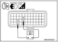
1.CHECK CVT FLUID TEMPERATURE SENSOR CIRCUIT
- Turn ignition switch OFF.
- Disconnect TCM connector.
- Check resistance between TCM vehicle side harness connector terminals.

2.CHECK HARNESS BETWEEN TCM AND CVT UNIT (CVT TEMPERATURE SENSOR) (PART 1)
- Disconnect CVT unit connector.
- Check continuity between TCM vehicle side harness connector terminals and CVT unit vehicle side harness connector terminals.

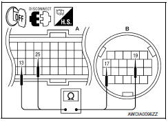
3.CHECK HARNESS BETWEEN TCM AND CVT UNIT (CVT TEMPERATURE SENSOR) (PART 2)
Check continuity between TCM vehicle side harness connector terminals and ground.

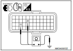
4.CHECK CVT FLUID TEMPERATURE SENSOR
Check CVT fluid temperature sensor. Refer to TM-56, "Component Inspection (CVT Fluid Temperature Sensor)".
5.DETECT MALFUNCTIONING ITEMS
Check TCM connector pin terminals for damage or loose connection with harness connector.
Component Inspection (CVT Fluid Temperature Sensor)
1.CHECK CVT FLUID TEMPERATURE SENSOR
Check resistance between CVT unit connector terminals.

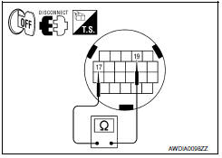
 P0705 transmission range switch A
Description
The Transmission range switch is included in the control valve
assembly.
The Transmission range switch includes 4 transmission position
switches.
TCM judges ...
 P0715 input speed sensor A
Description
The primary speed sensor detects the primary pulley revolution speed and
sends a signal to the TCM.
DTC Logic
DTC DETECTION LOGIC
DTC CONFIRMATION PROCEDURE
CAUTION:
Always driv ...
Other materials:
P0441 evap control system
DTC Logic
DTC DETECTION LOGIC
NOTE:
If DTC P0441 is displayed with other DTC such as P2122, P2123, P2127, P2128 or
P2138, first perform
trouble diagnosis for other DTC.
In this evaporative emission (EVAP) control system, purge flow occurs during
non-closed throttle conditions.
Purge vo ...
U1200 AV control unit
Description
Replace the AV control unit if this DTC is displayed.
Part name
Description
AV CONTROL UNIT
It is the master unit of the MULTI AV system and it is connected
to each control unit by means of communication. It operates each
syste ...
Instrument lower panel LH
Removal and Installation
REMOVAL
Using a suitable tool, gently remove the instrument side finisher
(LH) (1).
Remove the instrument lower panel (LH) (1).
Open the fuse block cover and remove the instrument lower panel screw
(A).
Disconnect the harness connectors and aspirator ...
Nissan Maxima Owners Manual
- Illustrated table of contents
- Safety-Seats, seat belts and supplemental restraint system
- Instruments and controls
- Pre-driving checks and adjustments
- Monitor, climate, audio, phone and voice recognition systems
- Starting and driving
- In case of emergency
- Appearance and care
- Do-it-yourself
- Maintenance and schedules
- Technical and consumer information
Nissan Maxima Service and Repair Manual
0.008
